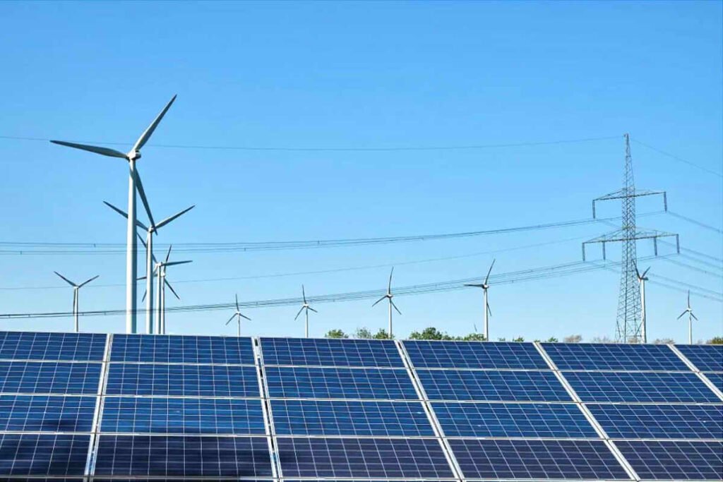
Pemilihan kabel udara untuk tumbuhan fotovoltaik adalah aspek penting dalam reka bentuk dan operasi yang cekap kemudahan tersebut. Ukuran konduktor udara yang betul secara langsung memberi kesan kepada keselamatan, kerugian tenaga, kos operasi, dan keuntungan jangka panjang.

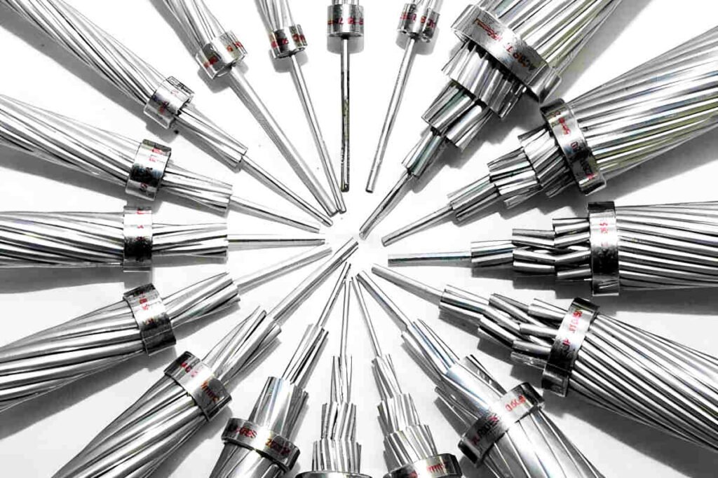
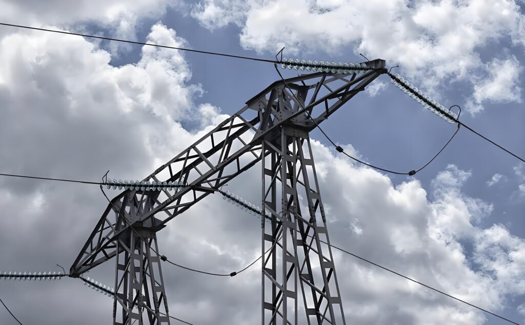
Tumbuhan fotovoltaik dibahagikan kepada tumbuhan fotovoltaik berpusat dan diedarkan berdasarkan kaedah kapasiti dan penggunaannya. Tumbuhan berpusat mempunyai kapasiti yang lebih tinggi dan biasanya disambungkan ke grid menggunakan tahap voltan 35kV/110kV atau lebih tinggi, mengakses pencawang 35kV/110kV yang berdekatan. Pencawang 35kV/110kV biasanya terletak di pusat beban bandar, pada jarak tertentu dari kilang fotovoltaik. Untuk mengurangkan kos dan meningkatkan kecekapan, kabel udara kosong biasanya digunakan untuk menyambungkan tumbuhan ke pencawang.
Semasa merancang tumbuhan fotovoltaik dan memilih kabel, Menggunakan konduktor kosong dengan keratan rentas yang lebih kecil mengurangkan penggunaan logam bukan ferus, dengan itu menurunkan kos pelaburan. Sebaliknya, Sekiranya konduktor dengan keratan rentas yang lebih besar digunakan, rintangan per unit panjang berkurangan, yang mengurangkan kerugian tenaga aktif, titisan voltan, dan kehilangan tenaga elektrik, Oleh itu, menurunkan kos operasi. Untuk mengurangkan kerugian dalam grid dan meningkatkan kecekapan ekonomi loji fotovoltaik, memaksimumkan pendapatan penjanaan tenaga, Adalah penting untuk memilih keratan rentas konduktor dengan betul.
Tiga syarat yang diperlukan untuk memilih keratan rentas konduktor
Pemilihan keratan rentas konduktor overhead mesti memastikan keselamatan orang, Bekalan elektrik yang boleh dipercayai, Teknologi Lanjutan, dan ekonomi yang munasabah. Secara teknikal, Pemilihan mesti memenuhi tiga syarat yang diperlukan:
Keadaan rintangan mekanikal
Semasa operasi jangka panjang, konduktor akan tertakluk kepada pelbagai daya luaran, seperti ketegangan garis, berat badan konduktor sendiri, angin, dan berat ais terkumpul. Untuk memastikan keselamatan dan kebolehpercayaan operasi konduktor, adalah perlu untuk mempunyai rintangan mekanikal yang mencukupi. Peraturan menyatakan bahawa untuk memastikan rintangan mekanikal garis kuasa, Keratan rentas konduktor tidak boleh kurang daripada nilai yang ditunjukkan dalam jadual berikut:
| Jenis konduktor | Melalui kawasan kediaman | Melalui kawasan bukan kediaman |
|---|---|---|
| Kabel aluminium dan aluminium aluminium | 35 | 25 |
| Kabel braided teras keluli | 25 | 16 |
| Kabel tembaga | 16 | 16 |
Keadaan pemanasan
Apabila semasa mengalir melalui konduktor, ia menjadi panas kerana rintangan. Untuk mengelakkan konduktor daripada terbakar atau penuaan sebelum ini disebabkan oleh terlalu panas, dan memastikan operasi jangka panjangnya yang selamat dan boleh dipercayai, Ia juga mesti memenuhi keadaan kenaikan suhu. Itu, Arus beban berterusan maksimum yang mengalir melalui konduktor mestilah kurang daripada arus berterusan selamat jangka panjang. Standard ini menetapkan arus berterusan selamat jangka panjang untuk suhu ambien 25 ° C, seperti yang ditunjukkan dalam jadual berikut:
| Keratan rentas / mm² | 35 | 50 | 70 | 95 | 120 | 150 | 185 | 240 | 300 | 400 | 500 |
|---|---|---|---|---|---|---|---|---|---|---|---|
| LJ | 170 | 215 | 265 | 325 | 375 | 440 | 500 | 610 | 680 | 830 | 980 |
| LGJ | 170 | 220 | 275 | 335 | 380 | 445 | 515 | 610 | 700 | 800 | – |
| LJGQ | – | – | – | – | – | – | 510 | 610 | 710 | 845 | 966 |

Keadaan kesan korona
Dalam garis udara voltan yang lebih tinggi, Keamatan medan elektrik sekitarnya tinggi. Ini dapat menyebabkan berlakunya pelepasan separa atau lengkap, Meningkatkan kerugian tenaga, Menjana gangguan komunikasi, dan mempercepatkan pengoksidaan peralatan. Untuk mengelakkan kesan korona, Keamatan medan elektrik di udara sekitar mesti dikurangkan dengan meningkatkan keratan rentas konduktor. Apabila tahap voltan berada di bawah 60kV, a Kesan Corona Lengkap tidak berlaku kerana voltan operasi yang rendah dan intensiti medan elektrik yang rendah. Namun begitu, Apabila tahap voltan sama dengan atau lebih besar daripada 110kV, Keratan konduktor minimum yang diperlukan untuk mengelakkan kesan korona adalah seperti berikut:
| Voltan Nominal / kV | 110 | 220 | 330 |
|---|---|---|---|
| Keratan konduktor minimum | LGJ-70 | LGJ-300 | LGJ-2 × 240 |
Kaedah untuk memilih keratan rentas konduktor 1: Kaedah ketumpatan semasa ekonomi
Apabila mempertimbangkan ekonomi dalam memilih keratan rentas konduktor, adalah perlu untuk memanfaatkan pelaburan dalam pembinaan talian dan kos operasi tahunan, yang terutamanya berdasarkan kerugian tenaga. Untuk memastikan daya maju ekonomi pemilihan konduktor, ia harus berdasarkan kepadatan semasa ekonomi. Setelah secara komprehensif mempertimbangkan prinsip manfaat keseluruhan (pelaburan, kos operasi, kadar pemulihan pelaburan, kadar susut nilai), Arus yang paling ekonomik sepadan dengan unit keratan rentas konduktor dipanggil ketumpatan semasa ekonomi. Ini berkaitan dengan bahan konduktor, pekali penggunaan garis, dan jumlah pelaburan. Dalam amalan, ia ditentukan berdasarkan bahan konduktor, jam penggunaan beban maksimum, dan voltan nominal, seperti yang ditunjukkan dalam jadual. Keratan rentas yang dipilih mengikut ketumpatan semasa ekonomi disebut sebagai keratan rentas ekonomi, ditakrifkan sebagai:
SJ = IMAX / J
- SJ: Keratan rentas ekonomi
- J: Ketumpatan semasa ekonomi
- IMAX: Arus operasi maksimum konduktor dalam keadaan biasa
| T(maks)/h | 2000 | 3000 | 4000 | 5000 | 6000 | 7000 |
|---|---|---|---|---|---|---|
| LJ konduktor 10 KV atau kurang | 1.44 | 1.18 | 1.00 | 0.86 | 0.76 | 0.66 |
| Konduktor LGJ of 10 KV atau kurang | 1.70 | 1.38 | 1.18 | 1.00 | 0.88 | 0.78 |
| Konduktor LCJ of 35 KV atau lebih | 1.86 | 1.50 | 1.26 | 1.08 | 0.94 | 0.84 |
Contoh memilih kabel udara untuk kilang fotovoltaik

Senario sebenar
Untuk a Penyelesaian kabel fotovoltaik, dalam talian udara 35kv, Kabel braided aluminium teras keluli dengan litar berganda digunakan, dengan panjang 15 km dan beban maksimum 16 MW pada akhir. Faktor kuasa purata adalah 0.9, dan kejatuhan voltan maksimum yang dibenarkan 5% Dalam keadaan normal dibenarkan. Keratan rentas konduktor perlu dipilih.
Pelan pemilihan
Keratan rentas konduktor akan dipilih berdasarkan ketumpatan semasa ekonomi, dan kemudian ia akan disahkan mengikut tiga syarat yang diperlukan dan penurunan voltan yang dibenarkan.
Arus operasi maksimum:
IMAX = (P / 2) / (1.732 × un × cosθ) = (16000 / 2) / (1.732 × 35 × 0.9) = 146.63 A
Dengan arus operasi maksimum (IMAX) dari 146.63 A dan tmax dari 2000 jam, Jadual menunjukkan bahawa ketumpatan semasa ekonomi (J) adalah 1.65 A/mm². Oleh itu, keratan rentas ekonomi adalah:
SJ = IMAX / J = 146.63 / 1.65 = 88.87 mm²
Keratan rentas terdekat dipilih: Pemandu LGJ-95, dengan parameter ro + jxo = 0.332 + J0.4 Ω/km dan arus berterusan selamat jangka panjang 335 A.
Pengesahan
- Rintangan mekanikal:
S = 95 mm² > Dan = 25 mm²
Memenuhi keperluan. - Keadaan pemanasan:
Oleh kerana garis litar berganda dapat beroperasi dalam satu litar, arus dalam talian meningkat, menjana lebih banyak haba. Ini adalah senario operasi yang paling kritikal. Dalam pengesahan suhu, mod operasi ini mesti dipertimbangkan:
IMAX = 2 × 146.63 A = 293.26 A < Iy = 335 A
Memenuhi keperluan. - Keadaan kesan korona:
Sejak garis itu 35 kV, tidak perlu mengesahkan keadaan kesan korona. - Penurunan voltan:
ΔU = (P × r + Q × x) × l / U = 1.80 kV
U% = 1.80 / 35 = 5.15% > 5%
Tidak memenuhi syarat, Oleh itu, keratan rentas konduktor mesti ditingkatkan. Konduktor LGJ-120 dipilih, dengan parameter ro + jxo = 0.236 + J0.421 Ω/km dan arus berterusan selamat jangka panjang 380 A.
Pengesahan baru:
- Rintangan mekanikal:
S = 120 mm² > Dan = 25 mm²
Memenuhi keperluan. - Keadaan pemanasan:
IMAX = 2 × 146.63 A = 293.26 A < Iy = 380 A
Jadual menunjukkan bahawa konduktor LGJ-120 mempunyai arus selamat maksimum 380 A dalam mod kegagalan, lebih besar daripada arus maksimum dalam konduktor, Jadi ia memenuhi syarat. - Keadaan kesan korona:
Sejak garis itu 35 kV, tidak perlu mengesahkan keadaan kesan korona. - Penurunan voltan:
ΔU = (P × r + Q × x) × l / U = 1.60 kV
U% = 1.60 / 35 = 4.57% < 5%
Memenuhi keperluan.
Oleh itu, LGJ-120 konduktor udara yang dipilih sesuai.
Kesimpulan
Pemilihan yang betul dari kabel di kilang fotovoltaik penting untuk memastikan keselamatan dan kecekapan. Dengan mempertimbangkan tiga kriteria utama -rintangan mekanikal, pemanasan, dan keadaan korona - dijamin bahawa konduktor akan menahan tuntutan fizikal dan terma, meminimumkan kerugian tenaga dan mengoptimumkan kos operasi.
Menggunakan kaedah ketumpatan semasa ekonomi membolehkan mengimbangi pelaburan awal dan kos jangka panjang. Dengan menyesuaikan keratan rentas konduktor untuk memenuhi keperluan teknikal dan mengelakkan titisan voltan, operasi pemasangan yang cekap dan kos efektif dipastikan, memaksimumkan prestasi dan ketahanannya.

