
As the world shifts towards renewable energy, solar power has emerged as one of the most popular and sustainable sources of electricity. Solar projects, whether residential or commercial, require careful planning and consideration, especially when it comes to selecting the right components. Among these components, cables play a critical role in ensuring the efficiency, safety, and longevity of the solar power system.
Table of Contents
- Solar System Power Generation Process
- What Types of Cables Are Needed for Solar Power Systems?
- What Percentage of the Total Construction Cost Do Cables Represent in a Photovoltaic Power Station?
- About Solar DC Cables
- Why Use Special Cables for Photovoltaic Systems?
- What Is TÜV Certification for Solar Cables?
- What Specifications Should Be Chosen for H1Z2Z2-K PV Cables?
- What Are the Differences Between DC and AC Applications of H1Z2Z2-K Photovoltaic Cables?
- What Are the Differences Between H1Z2Z2-K and PV1-F Photovoltaic Cables?
- How to Select PV1-F Cable Specification?
- Why Are Solar Cables Split into Red and Black?
- Can You Make Solar Cable Connectors by Yourself?
- What Are the Commonly Used Solar Connectors?
- About Solar AC Cables
- About Cables for Grounding System
- Why Should Solar Power Generation Systems Be Grounded?
- What Grounding is Required in Solar Power Systems?
- How Are Solar Panels Grounded?
- Why Should the Frames of Solar Panels Be Connected and Grounded?
- Which Material Should Be Used for Grounding Rod in Photovoltaic Systems?
- What Specifications of Earth Rods Are Commonly Used?
- How Should Earth Rods Be Installed in Photovoltaic Systems?
- Overhead Cables, Control Cables and Communication Cables in PV Projects
- Legal and Regulatory Requirements for Cable Routing in Solar Projects
- Best Practices for Cable Routing
- Essential Advice for Buying Cables
- Final Thoughts
Selecting the appropriate cables for your solar project can be a daunting task, given the variety of options available and the specific requirements of photovoltaic (PV) systems. This guide aims to provide a comprehensive overview of everything you need to know about buying cables for your solar project. From understanding the solar power generation process to selecting the right types of cables for different applications, we will cover all the essential aspects to help you make informed decisions.
By the end of this guide, you will have a clear understanding of the critical factors to consider when buying cables for your solar project, ensuring that your system operates efficiently and safely for years to come.
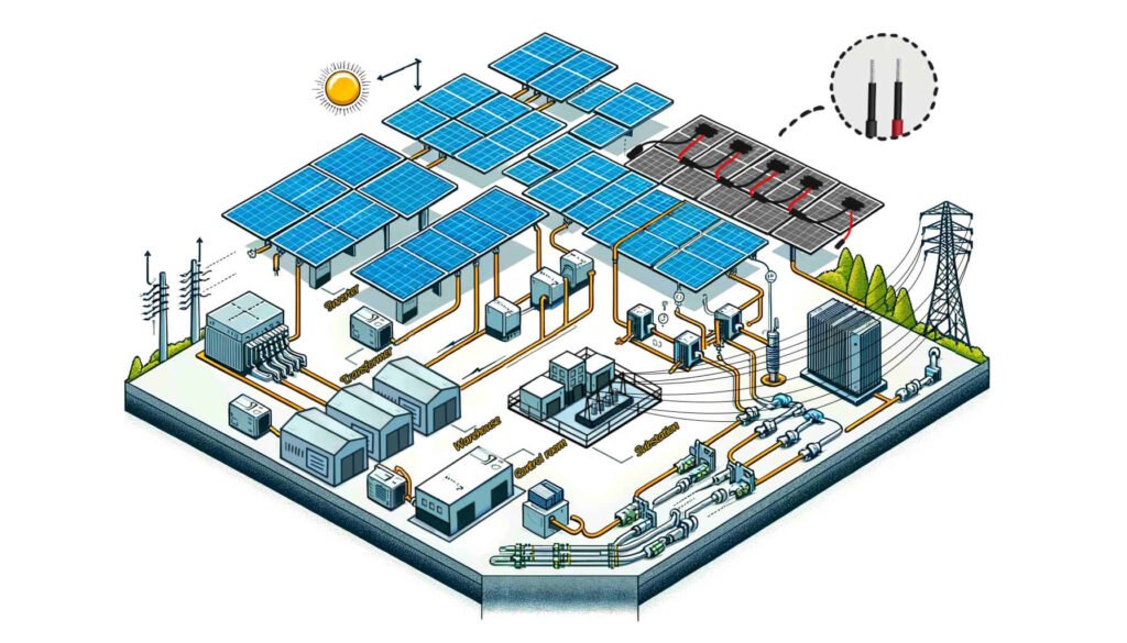
Solar System Power Generation Process
Understanding the processes of solar system power generation is crucial for selecting the right cables and components for your PV project. Proper cable selection ensures the efficient and safe transmission of electricity throughout the system, whether it’s a grid-connected or off-grid setup.
1. Solar Panels Capture Sunlight
Solar panels, composed of numerous solar cells, capture sunlight when photons (light particles) strike the surface. These photons transfer their energy to the electrons within the solar cells, creating an electrical current.
2. Electricity Generation
The energy from the photons energizes the electrons, causing them to flow and produce a direct current (DC). Solar panels are typically arranged in large arrays to generate significant amounts of electricity, sufficient to power homes, businesses, or entire communities.
3. Inverter Conversion
The DC electricity generated by the solar panels cannot be used directly by most household appliances and commercial equipment, which operate on alternating current (AC). To bridge this gap, an inverter is used to convert the DC electricity to AC electricity, making it compatible with standard electrical systems.
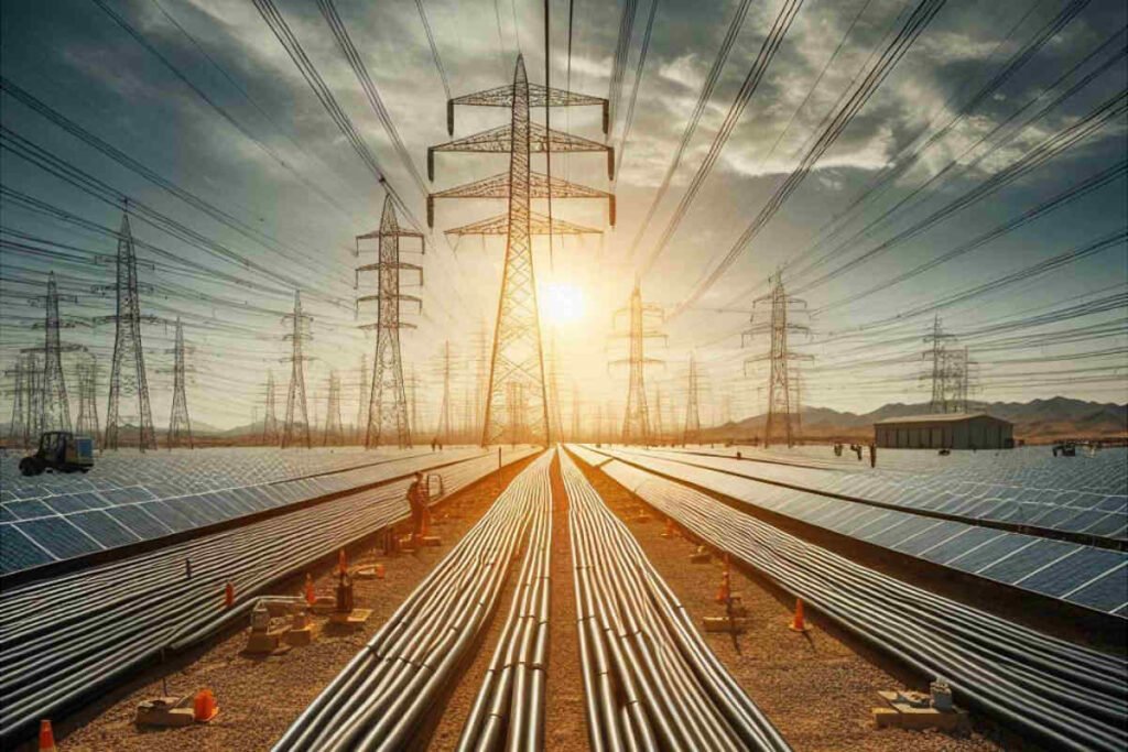
4. Transmission and Distribution
After conversion to AC, the electricity is sent to a transformer. The transformer increases the voltage of the electricity, which allows it to be transmitted efficiently over long distances through power lines. The high-voltage AC power is then distributed through the grid to various consumers, including homes and businesses.
Grid-Connected Systems
In grid-connected systems, the process is as follows:
- PV Panels Generate DC Power: Solar panels capture sunlight and generate DC power.
- Inverter Converts to AC Power: The DC power is converted to AC power by the inverter.
- Transformer Boosts Voltage: If necessary, a transformer increases the voltage for efficient transmission.
- Transmission to the Grid: The AC power is transmitted through overhead lines to the grid.
In this system, the electrical energy is converted between DC and AC only once at the inverter stage. After conversion, the electricity is transmitted and used in AC form.
Off-Grid Systems
In off-grid systems, the process is slightly different:
- PV Panels Generate DC Power: Solar panels capture sunlight and generate DC power.
- Inverter Converts to AC Power: The DC power is converted to AC power by the inverter.
- Transformer Boosts Voltage: If needed, a transformer increases the voltage.
- Direct Use or Storage: The AC power can be directly connected to the user’s grid for immediate use or stored in batteries for later use.
Off-grid systems rely on battery storage to ensure a continuous power supply, even when sunlight is not available, such as during nighttime or cloudy days.
After knowing the process of solar power generation, we can determine which cables are needed for the whole system.
What Types of Cables Are Needed for Solar Power Systems?
As a crucial component of sustainable energy solutions, the safe and efficient operation of solar power generation systems relies on the appropriate configuration and use of various specialized cables. The types of cables required in a solar power generation system include the following:
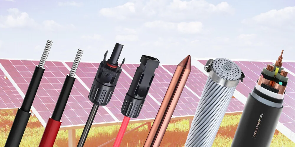
Solar DC Cable
These cables are specifically designed for connecting photovoltaic modules (solar panels) and for power transmission between modules to the DC combiner box. Given their direct exposure to outdoor environments, they must possess the following characteristics:
- UV Resistance: To prevent performance degradation due to prolonged sun exposure.
- Weather Resistance: To withstand various weather conditions, including extreme temperatures, humidity, and wind-blown sand.
- Salt Spray Corrosion Resistance: Suitable for coastal areas to prevent salt damage.
- Flame Retardancy: To reduce fire risks and enhance system safety.
- Mechanical Strength: To endure installation and environmental pressures without being easily damaged.
AC Cable
AC cables are used at the inverter output end to transmit the converted AC power to the AC distribution board or directly into the grid. These cables need to meet grid connection standards and possess good insulation properties and heat resistance to ensure safe and efficient power transmission.
Data Communication Cable
In a solar power generation system, data communication cables act as the information bridge. They not only transmit the electrical data generated by the photovoltaic array but also convey real-time status information of inverters and other monitoring equipment to the central monitoring system via wired or wireless networks (including fiber optics) for system optimization and fault diagnosis.
Control Cable
Control cables are used to connect controllers, inverters, and other auxiliary equipment within the system, ensuring automated control and effective monitoring. These cables need to have good signal transmission stability and anti-interference capabilities to ensure accurate execution of control commands.
Grounding Cable
Grounding cables play a critical role in the safety protection of the entire solar power generation system. They provide a low-resistance path to quickly discharge lightning currents or system fault currents, preventing electric shocks and equipment damage, thereby ensuring the safety of personnel and equipment.
Overhead Cable
In certain installation scenarios, such as long-distance transmission or terrain constraints, overhead cables are used for grid connection of the solar power generation system. These cables need to be specially designed to resist external physical damage and climatic factors while maintaining good conductivity and mechanical strength.
When selecting these solar cables, it is essential not only to consider their characteristics and applicable environments but also to ensure that all cables and accessories comply with local electrical safety standards and industry regulations to ensure the long-term stable operation and compliance of the solar power generation system.
What Percentage of the Total Construction Cost Do Cables Represent in a Photovoltaic Power Station?
The cost of cables in a photovoltaic (PV) power station typically represents around 10% of the total construction cost. This percentage can vary based on several factors such as the scale of the project, equipment selection, regional differences, and market fluctuations. According to some estimates:
- Photovoltaic modules (solar panels) account for approximately 50% of the total equipment cost.
- Inverters and other electrical equipment account for about 10%.
- Cables and mounting structures each account for around 10%.
Therefore, cable costs generally make up about 10% of the total construction cost. However, this is a rough estimate, and the actual proportion may vary depending on the specific budget and material prices of a project. Additionally, with advancements in technology and market changes, this percentage may be subject to adjustments.
About Solar DC Cables
Why Use Special Cables for Photovoltaic Systems?
Photovoltaic cables are specifically designed for photovoltaic power generation projects, with insulation and sheathing characteristics that ordinary cables do not possess.
If ordinary cables are used in PV system, they are prone to failure in harsh outdoor environments, greatly reducing the lifespan of the entire solar power system. Additionally, it can lead to current overload, severe voltage drop, frequent generation faults, and low generation efficiency in photovoltaic power plants, even potentially causing fires in the plant.
Therefore, to ensure the long-term stable operation of photovoltaic power plants for 25 years, it is essential to choose cables specifically designed for photovoltaic systems, such as H1Z2Z2-K or PV1-F.
What Is TÜV Certification for Solar Cables?
TÜV Solar Cable Certification refers to a series of certificates awarded to cables that have been tested, inspected and certified by an independent third party of the TÜV Rheinland Group, headquartered in Germany, in accordance with specific standards.
As a special type of cable, the safety and performance of photovoltaic cables are crucial for solar power generation systems, hence they undergo rigorous testing and certification to ensure their quality and reliability.
Regarding TÜV certification for PV cables, its development has progressed from the 2PfG 1169/08.2007 standard to the EN 50618:2014 standard. The most recent standard is IEC FDIS 62930, but most solar cable certifications still adhere to the valid EN 50618 standard.
What Specifications Should Be Chosen for H1Z2Z2-K PV Cables?
In typical photovoltaic systems, the most common options are H1Z2Z2-K 1×4 and H1Z2Z2-K 1×6 cables. Generally, larger cable cross-sections indicate greater load-bearing capacities.
Considerations such as working voltage, current capacity, and environmental temperature range should also be factored in. After determining the voltage and current requirements, refer to the parameter table of H1Z2Z2-K cables to select the appropriate specification.
If you encounter uncertainty in selecting cable specifications, our ZMS technical team is available to offer tailored solutions.
Learn more about H1Z2Z2-K solar cable
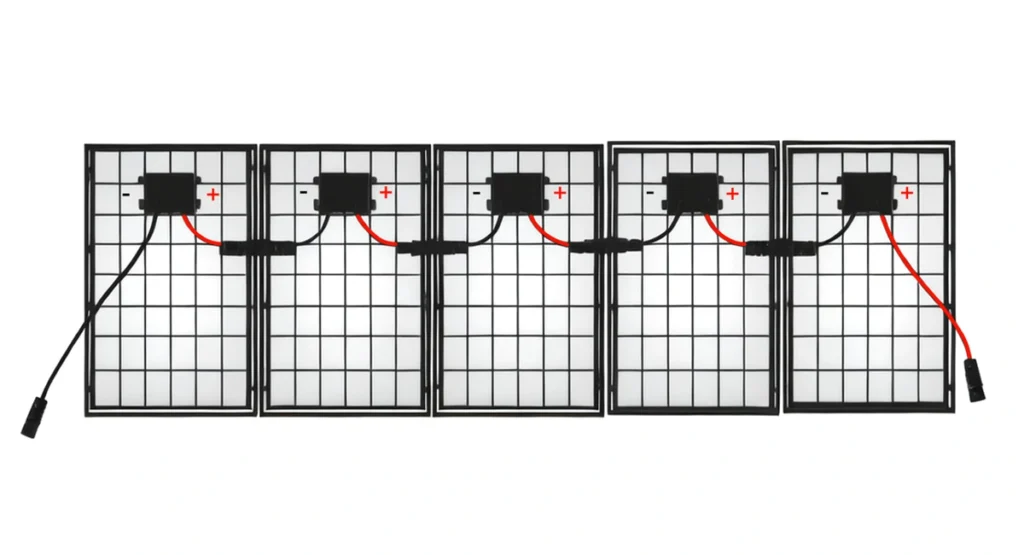
What Are the Differences Between DC and AC Applications of H1Z2Z2-K Photovoltaic Cables?
H1Z2Z2-K cables can be used for both DC circuits (1.5kV) and AC circuits (1.0/1.0kV). In photovoltaic power generation systems, their specific application differences are as follows:
For DC Applications:
- Series connection between photovoltaic modules
- Parallel connection between strings
- Parallel connection from strings to DC distribution boxes
- Connection from DC distribution boxes to inverters
For AC Applications:
- Connection from inverters to step-up transformers
- Connection from step-up transformers to distribution devices
- Connection from distribution devices to the grid or users
What Are the Differences Between H1Z2Z2-K and PV1-F Photovoltaic Cables?
PV1-F cable is an older version solar cable that complies with the TÜV 2Pfg1169 standard, and its standard certification has ceased updating. In contrast, the H1Z2Z2-K photovoltaic cable complies with the latest TÜV EN50618:2014 certification.
The voltage ratings differ between PV1-F and H1Z2Z2-K cables. PV1-F has a voltage rating of DC: 1.0kV and AC: Uo/U: 0.6/1.0kV, while H1Z2Z2-K has a voltage rating of DC: 1.5kV and AC: Uo/U: 1.0/1.0kV. H1Z2Z2-K can provide higher transmission efficiency and stability.
In terms of structure, PV1-F cable has a single insulation layer, whereas H1Z2Z2-K cable adopts a dual-layer insulation structure. This make H1Z2Z2-K cable superior in durability and protection, especially against mechanical damage and environmental factors.
In summary, H1Z2Z2-K solar cable is more advanced in design, offering higher electrical and mechanical performance, suitable for more demanding application environments. On the other hand, PV1-F solar cable is primarily advantageous in cost-effectiveness, suitable for most conventional photovoltaic systems.
For cost-effectiveness considerations, PV1-F cable can be used for series connections between photovoltaic modules and parallel connections from strings to DC distribution boxes. Meanwhile, H1Z2Z2-K cable can be used for connections between distribution boxes and inverters, as well as for direct current connections in large inverters.
How to Select PV1-F Cable Specification?
Currently, the most commonly used photovoltaic DC cable is the PV1-F 1×4 cable. However, with the increase in photovoltaic module currents and single inverter power, the application of PV1-F 1×6 DC cables is also increasing.
According to relevant specifications, it is generally recommended that the loss of photovoltaic DC power lines should not exceed 2%. In DC circuits, the line resistance of PV1-F 1x4mm² cable is 4.6mΩ/m, and the line resistance of PV1-F 1x6mm² cable is 3.1mΩ/m. Assuming a working voltage of 600V for DC modules, a 2% voltage drop loss is 12V. Assuming a module current of 13A, when using 4mm² DC cable, the recommended maximum distance from the furthest module end to the inverter should not exceed 120 meters (single string, excluding positive and negative poles). If it exceeds this distance, it is recommended to choose 6mm² DC cable, but the recommended maximum distance from the furthest module end to the inverter should not exceed 170 meters.
To reduce system costs, photovoltaic power plants now rarely configure modules and inverters in a 1:1 ratio. Instead, they design a certain amount of overcapacity based on factors such as sunlight conditions and project requirements. For example, for a 110KW module, a 100KW inverter is selected, and it is calculated based on a 1.1x overcapacity on the AC side of the inverter. The maximum AC output current is approximately 158A. AC cables are selected based on the maximum output current of the inverter. Because regardless of how much the modules are overconfigured, the AC input current of the inverter will never exceed the maximum output current of the inverter.
Learn more about PV1-F solar cable
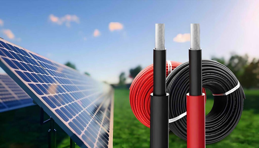
Why Are Solar Cables Split into Red and Black?
In the photovoltaic industry, using red and black cables has become a widely accepted method of identification. Their primary purpose is to distinguish between positive and negative poles. In DC circuits, typically, red solar wires indicate the positive pole of the current, while black solar wires indicate the negative pole. This color differentiation helps quickly identify the polarity of photovoltaic connections during the installation and maintenance of solar systems, thus preventing wiring errors.
Can You Make Solar Cable Connectors by Yourself?
The process of making solar cable connectors includes checking for damage to male and female cores and heads, and using wire strippers, crimping tools, and open-end wrenches. Even non-professionals can make these connectors by following specific steps.
Compared to making connectors yourself, directly customizing solar panel extension cables may be slightly more expensive, but it can save time and labor and make installation more convenient.
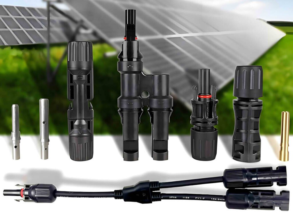
What Are the Commonly Used Solar Connectors?
The most commonly used connector type in solar photovoltaic systems is the MC4 connector. It has become one of the standards for photovoltaic connectors due to its widespread use and market recognition. MC4 connector extension cables can withstand high voltage and current and are suitable for connecting solar panels, inverters, and other system components.
ZMS’s MC4 compatible connectors are consistent with MC4 connectors in specifications, size, and tolerance and can be 100% matched.
In addition to MC4 connectors, other commonly used solar connectors include Y-type or parallel connectors. Their structure is a one-to-many connector, which can connect multiple solar panels in series to increase the voltage of the entire panel array while keeping the current constant.
Learn more about Solar Cable Connector
About Solar AC Cables
How Should AC LV Cables Be Selected for Solar Power Projects?
When a solar power station is close to the load center or is itself a distributed generation, you only need to use low-voltage cables to directly connect to a three-phase 400V or single-phase 230V low-voltage distribution network. To connect to a medium or high-voltage grid, low-voltage cables must first be used to connect to a transformer.
The AC voltage output by the inverter usually comes in various standards. For example, the output voltage of a central inverter can be 315V, 360V, 400V, and so on, while the output voltage of a string inverter can be 480V, 500V, 540V, 800V, and so on.
Therefore, in PV systems, it is generally possible to use low-voltage cables with a rated voltage of 450/750V, 0.6/1 kV, or 1.8/3 kV. Depending on whether the cable is buried or not, an armored layer may be added.
Learn more about AC Solar Cable
How Should AC MV Cables Be Selected for Solar Power Projects?
If a photovoltaic power generation system needs to connect to a medium or high-voltage grid, low-voltage cables must first be used to connect to a transformer, which will then step up the voltage to the appropriate level. Medium-voltage cables are then used to deliver power to the substation. The number of medium-voltage cables required depends on the connection method.
Traditional Star Structure
In the traditional star structure, each transformer has a single medium-voltage output line connecting to the substation. This structure is the simplest and most straightforward, and it is commonly used in the design of photovoltaic power stations. Each cable only carries the power of a single transformer, so the cable specifications are smaller, reducing costs. However, since each transformer has only one line connecting to the substation, the reliability is not very high.
Single-Output Ring Structure
The single-output ring structure connects several transformers in a ring using cables, and the closest transformer to the substation is connected to the substation using medium-voltage cables. Compared to the double-output ring structure, the single-output ring structure uses fewer medium-voltage AC solar cables. However, because the entire ring has only one line connecting to the substation, the reliability is lower.
Double-Output Ring Structure
The double-output ring structure has an additional line connecting the ring to the substation compared to the single-output ring structure. If one output line fails, the other line can continue to allow the inverters in the ring to output power to the grid. Similar to the single-output ring structure, considering the flow direction during a fault, all cables must be selected to withstand the power of all transformers, resulting in relatively higher costs.
Bridge Structure
Before the ring structure was proposed, the bridge structure was often used. In this structure, based on the star structure, each pair of adjacent transformers is connected using medium-voltage cables. This way, each transformer has two lines connecting to the substation, greatly improving system reliability. However, the cost is relatively high due to the additional cables between each pair of transformers.
For photovoltaic power stations of different sizes, the cable selection analysis varies under different requirements. When selecting medium-voltage cables, it is essential to comprehensively consider mandatory requirements, costs, and benefits to determine the most advantageous solution and decision.
What Are the Principles for Selecting AC Cables for Solar Power Systems?
The selection of AC cables for solar projects follows the general requirements for cable selection, which include considering voltage levels, continuous operating current, short-circuit thermal stability, allowable voltage drop, economic current density, and installation environment conditions. Additionally, photovoltaic power generation has its own characteristics, requiring consideration for cables that may be used in harsh environmental conditions such as high temperatures, severe cold, and ultraviolet radiation. Therefore, the following factors should be taken into account:
- Insulation performance of the cable
- Heat resistance and flame retardancy of the cable
- Moisture resistance and UV protection of the cable
- Installation methods of the cable
- Type of cable conductor
- Cable specifications
About Cables for Grounding System
Why Should Solar Power Generation Systems Be Grounded?
Grounding in PV systems is one of the most frequently overlooked issues by PV installation personnel, especially in small-capacity PV systems where grounding and lightning protection are not given much attention.
However, if grounding is not done, errors can occur due to low insulation resistance to ground or excessive leakage currents, affecting power generation and potentially endangering personal safety. Additionally, unshielded or elevated metal parts are more susceptible to lightning strikes. Without grounding, equipment may be struck by lightning, causing significant damage to the PV power generation system.
Grounding in PV systems mainly includes grounding on the solar component side, inverter side, and distribution cabinet side. Proper grounding not only enhances the safety of the solar system but also extends its lifespan.
What Grounding is Required in Solar Power Systems?
Component-side Grounding:
- Module Frame Grounding: The aluminum frame of the module contacting the mount does not mean effective grounding. The grounding hole of the module needs to be connected to the mount for effective grounding. The grounding holes of the modules are typically used for string connections, with the grounding holes at both ends connected to the metal mount.
- Mount Grounding: Usually, round steel, galvanized steel rods, or copper-bonded steel rods are used for grounding, with the grounding resistance required to be no greater than 4Ω.
Inverter-side Grounding:
- Operational Grounding: The PE terminal of the inverter is connected to the PE busbar in the distribution box, which is grounded through the distribution box.
- Protective Grounding: The grounding hole of the inverter chassis is used for repeated grounding to protect the inverter and the safety of operators. The protective grounding of the inverter chassis can either use a separate grounding electrode or share one with the distribution box.
Distribution Box-side Grounding:
- Lightning Protection Grounding: AC-side lightning protection consists of fuses or circuit breakers and surge protection devices (SPD). The lower end of the SPD is connected to the grounding busbar of the distribution box.
- Box Grounding: According to regulations, the metal frame and base steel of the distribution box must be grounded or connected to neutral. The cabinet door and the cabinet body need cross-connection to ensure reliable grounding.
How Are Solar Panels Grounded?
Generally, grounding holes on the solar panels are used to connect between strings of panels. The panels at both ends of the string are connected to the metal frame, primarily using yellow-green solar earth cables.
For grounding the panel frames, copper bonded steel rods of φ10 or φ12 are typically used, buried 1.5 meters underground.
The grounding resistance of solar panels should not exceed 4Ω. If the grounding resistance requirement is not met, resistance-reducing agents are usually added, or the grounding rods are buried in areas with lower soil resistivity.
Learn more about Solar Grounding Cable
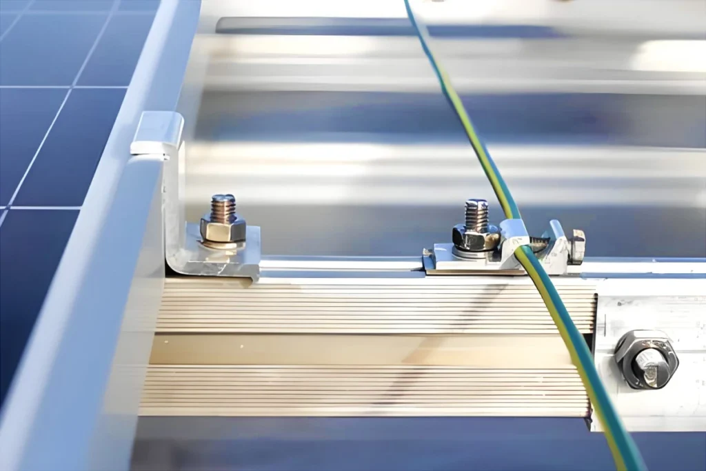
Why Should the Frames of Solar Panels Be Connected and Grounded?
Some people believe that since both the solar panels and their supporting structures are metal, grounding the supports alone is sufficient.
In reality, most solar panel aluminum frames and galvanized or aluminum alloy supports are coated, which does not meet grounding requirements. Additionally, solar panels can age over time, potentially leading to excessive leakage currents or low insulation resistance to ground. If the solar panel frames are not grounded, after a period of use, this can result in inverter failures, preventing the PV system from generating electricity properly.
When connecting solar panel frames to metal supports, it is necessary to remove the oxide layer from the metal surfaces to reduce grounding impedance, ensuring it meets grounding requirements.
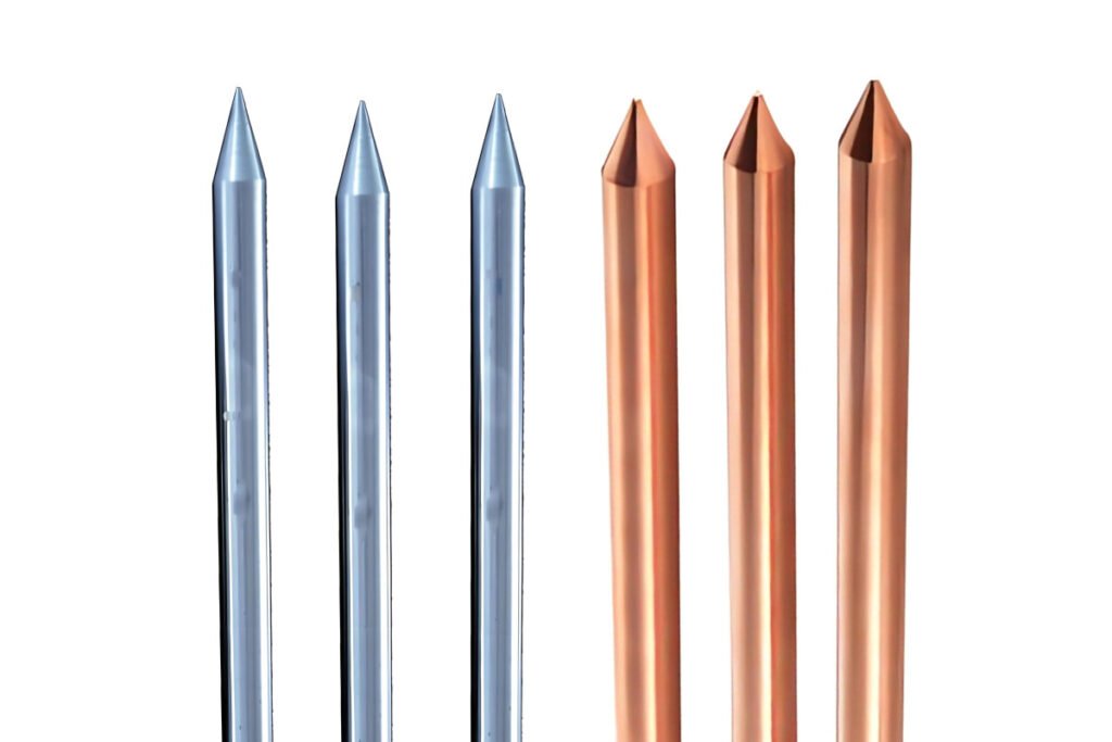
Which Material Should Be Used for Grounding Rod in Photovoltaic Systems?
Galvanized steel is cheaper, but it has many welded joints, resulting in lower construction efficiency and higher construction costs. Pure copper has excellent conductivity but is expensive. Copper-bonded steel, however, only costs 9.4% more than galvanized steel and offers a much longer service life. Therefore, copper bonded steel electric earth rods are typically chosen as the primary grounding material in solar power systems.
What Specifications of Earth Rods Are Commonly Used?
Copper-bonded Steel
In photovoltaic power systems, the horizontal grounding body of copper-bonded steel grounding materials commonly uses Φ10-Φ12 copper-bonded round steel, with a manufacturing length typically of 100 meters per reel. The grounding electrodes use Φ14 or Φ17.2 copper-bonded steel rods.
Connection method: Thermite welding (no external power or acetylene needed), using pure copper for joint materials, with no need for anti-corrosion measures at the welding points.
Galvanized Steel
In traditional grounding grids, horizontal grounding bodies made of hot-dip galvanized steel are generally designed with specifications of 50X5 or 60X6 galvanized flat steel, with a manufacturing length of 6 meters per piece. Vertical grounding electrodes use 50X5 hot-dip galvanized angle steel or Φ50 galvanized steel pipes, with a grounding electrode length of 2.5 meters per piece.
Connection method: Electric welding, with the welding points needing anti-corrosion treatment, such as two coats of anti-rust paint and one coat of asphalt paint.
Bare Copper
For pure copper grounding materials, the horizontal grounding body usually uses 25×4, 40×4, 50×5, or 60×6 mm copper strips, or S70/S95/S120/S150/S185/S240 mm bare copper wires. The vertical grounding body typically uses 16×2500 mm or 20×2500 mm copper rods, or 50×3000 mm or 55×2500 mm pure copper electrolytic ion grounding electrodes.
Connection method: Thermite welding, fire mud melting welding, or hot-melt welding.
Learn more about Earth Rod for PV System
How Should Earth Rods Be Installed in Photovoltaic Systems?
During construction, installing a ground rod is very flexible and can be adapted to the specific conditions on site. Various methods can be used, such as directly driving the electric ground rods into the soil with heavy hammers or electric hammers. In complex soil conditions where the rod cannot be driven in, a hole can be drilled first before installing the ground rod.
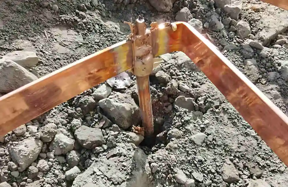
In uniform soil conditions, if using a heavy hammer for installation and driving a single rod, it is advisable to install a drill bit (impact-resistant bolt) on the pointed end of the rod to prevent damage to the copper layer when the rod is driven deep. For deeper grounding, multiple rods can be connected using connectors to achieve the desired length, ensuring good electrical connection.
In cases where deep drilling is difficult or impossible, drilling tools can be used to penetrate rocks. After drilling, there are two methods for installing the earth rods:
- Connect the rods to the desired length using connectors. Once drilled to the intended depth, fill the hole with a resistivity-reducing agent and add water until the hole is filled.
- Connect the rods to the desired length using connectors. After drilling to the intended depth, mix the resistivity-reducing agent with water and pour it into the hole to fully envelop the rod.
Overhead Cables, Control Cables and Communication Cables in PV Projects
Which Overhead Cable to Use in Solar Power Systems?
In grid-connected photovoltaic power generation systems, once the generated DC power is converted to AC power by the inverter and integrated into the AC grid, power transmission is often carried out via overhead lines. Typically, the grid connection process of photovoltaic power generation systems can occur in the following scenarios:
Direct Connection
For small distributed photovoltaic power generation systems, such as residential rooftop photovoltaics, the DC power can be directly converted to AC power through the inverter and then connected to the low-voltage grid via distribution lines. In this case, underground low-voltage cables and overhead insulated cables like ABC cables can be used.
Connection through Box Transformers or Substation Integration
Medium or commercial-scale photovoltaic power stations may use box-type substations (box transformers) to convert the DC power generated into AC power suitable for grid integration through the inverter, and then step up the voltage through the box transformer to match the voltage level of the overhead grid, before connecting to overhead lines.
Large-scale ground-mounted photovoltaic power stations typically require a transformer to step up the voltage to a higher level for efficient transmission. In this case, the power is directly connected to a substation, which then distributes it to high-voltage or ultra-high-voltage overhead grids.
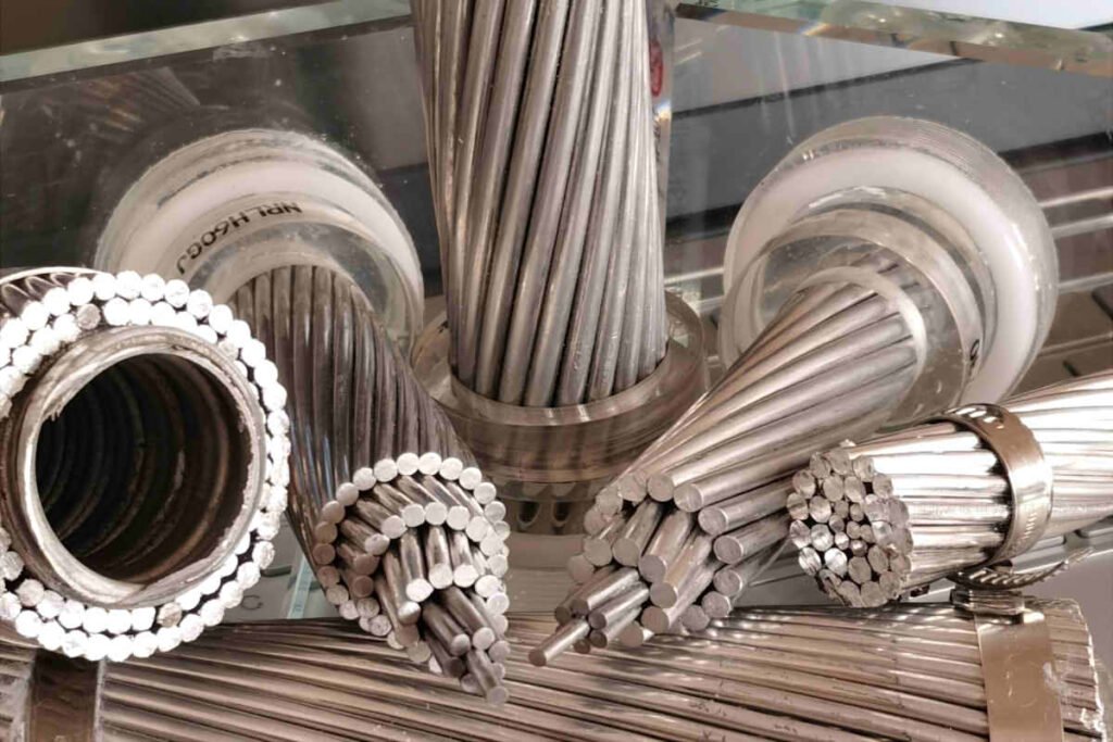
In these two scenarios, if the distance from the power station to the grid connection point is relatively short and the load is not large, AAC cable could be an economical choice. For medium distances or where better physical performance is required, AAAC cable may be a better option. For long-distance transmission or where special cable strength requirements are needed, especially when overhead lines need to cross complex terrain or withstand extreme weather conditions, ACSR conductor will be the most suitable choice.
Learn more about Overhead Cable for Solar System
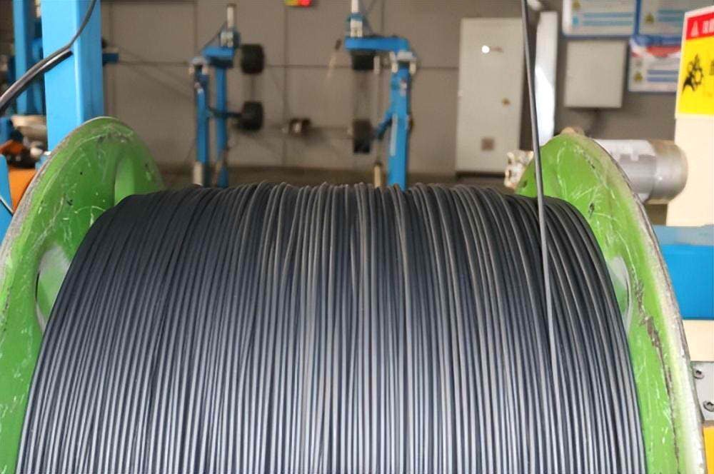
Do Communication Cables Affect the Accuracy of Solar Power Generation System Counting?
In a solar power generation system, the primary role of communication cables is to transmit control signals and monitoring data, such as power output, system status, fault alarms, and other information. These cables do not directly participate in the transmission of electrical energy. Therefore, communication cables themselves do not directly affect the accuracy of the counting in a solar power generation system.
However, if communication cables experience faults (such as signal attenuation, interference, or disconnections), it may lead to the monitoring system being unable to accurately receive or transmit data, thereby affecting the precision and timeliness of system monitoring. For example, data transmission delays or errors might prevent maintenance personnel from promptly understanding the actual operational status of the power generation system or lead to inaccurate data recording, thus impacting the statistics and analysis of power generation.
Therefore, while communication cables do not affect the actual production of electrical energy, they are crucial for the effective management and maintenance of the system. This indirectly relates to the overall performance evaluation and efficiency optimization of the solar power generation system. Ensuring the quality and proper maintenance of communication cables is essential for maintaining reliable monitoring and efficient operation of the solar power generation system.
Learn more about Communication and Control Cable for PV System
Legal and Regulatory Requirements for Cable Routing in Solar Projects
Understanding Regulatory Compliance
When planning and executing a solar project, it is essential to adhere to various legal and regulatory requirements to ensure safety, efficiency, and compliance with local, national, and international standards. Regulatory bodies and policies govern the installation and operation of solar power systems, including the routing and selection of cables. Understanding these requirements is crucial for the successful completion of your solar project.
Key Regulatory Bodies and Standards
National Electrical Code (NEC)
In the United States, the National Electrical Code (NEC) sets the standard for the safe installation of electrical wiring and equipment. Article 690 of the NEC specifically addresses solar photovoltaic (PV) systems, covering aspects such as wiring methods, grounding, and overcurrent protection. Adhering to NEC guidelines ensures that your cable routing meets safety and performance standards.
International Electrotechnical Commission (IEC)
The International Electrotechnical Commission (IEC) develops international standards for all electrical, electronic, and related technologies. IEC 62548:2016 provides guidelines for the design and installation of solar PV arrays, including cable management and routing. Compliance with IEC standards is often required for international projects.
Local Building Codes
Local building codes may impose additional requirements for solar installations, including cable routing. These codes can vary significantly by region, so it is essential to consult with local authorities and ensure compliance with all relevant regulations.
Best Practices for Cable Routing
Proper Labeling and Documentation
Ensure that all cables are properly labeled and that comprehensive documentation is maintained. This includes diagrams of cable routing, specifications of the cables used, and records of inspections and approvals. Proper documentation facilitates regulatory compliance and simplifies future maintenance.
Use of Conduits and Trays
Using conduits and cable trays for routing can protect cables from physical damage, reduce the risk of electrical faults, and enhance the overall safety of the installation. Ensure that conduits and trays meet the relevant standards and are properly installed.
Grounding and Bonding
Proper grounding and bonding are critical for the safety and performance of solar power systems. Ensure that grounding methods comply with NEC, IEC, and local standards. This includes using appropriate grounding conductors, connectors, and rods, and ensuring that all metallic components are adequately bonded.
Regular Inspections and Maintenance
Regular inspections and maintenance are essential to ensure that cable routing remains compliant with regulatory requirements and continues to operate safely and efficiently. Schedule periodic inspections to identify and address any issues, such as physical damage, wear, or corrosion.
Essential Advice for Buying Cables
Understand Your System Requirements
Before purchasing cables, it is vital to have a clear understanding of your solar system’s requirements. Consider the system’s size, the types of components used, and the environmental conditions. Ensure that the cables you choose can handle the expected electrical load and are suitable for the specific conditions of your installation site.
Prioritize Quality and Certification
Always opt for high-quality cables that are certified by reputable standards such as TÜV, UL, or IEC. Certified cables are tested for durability, safety, and performance, ensuring they meet industry standards. Using certified cables helps prevent potential issues such as power loss, overheating, or fire hazards.
Choose the Right Cable Types
Select cables that are specifically designed for solar applications. For DC applications, PV cables like H1Z2Z2-K and PV1-F are ideal due to their resistance to UV radiation, temperature variations, and mechanical stress. For AC applications, ensure that you use appropriate low and medium-voltage cables.
Consider Environmental Factors
Take into account the environmental conditions at the installation site. Cables exposed to harsh weather, UV radiation, or extreme temperatures should be chosen for their resilience to these conditions. Proper insulation and protective measures will extend the lifespan of the cables and maintain system efficiency.
Ensure Proper Installation and Maintenance
Proper installation is as crucial as selecting the right cables. Follow best practices for cable routing, grounding, and protection to avoid physical damage and electrical faults. Regular maintenance and inspections are essential to ensure the ongoing safety and performance of your solar power system.
Plan for Regulatory Compliance
Be aware of the local, national, and international regulations that apply to your solar project. Ensure that your cable selection and installation comply with these standards to avoid legal issues and ensure the safety and reliability of your system.
Final Thoughts
Investing time and resources into selecting the right cables for your solar project pays off in the long run. Quality cables ensure efficient power transmission, reduce maintenance costs, and enhance the overall safety and reliability of your system. By following the guidelines and best practices outlined in this guide, you can make informed decisions that contribute to the success of your solar installation.
Remember, a well-designed solar power system is not just about the panels and inverters; the cables that connect these components are equally important. Make sure to prioritize quality, compliance, and proper installation to harness the full potential of your solar energy system.