H1Z2Z2-K Cable
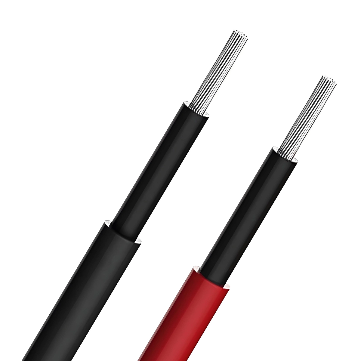
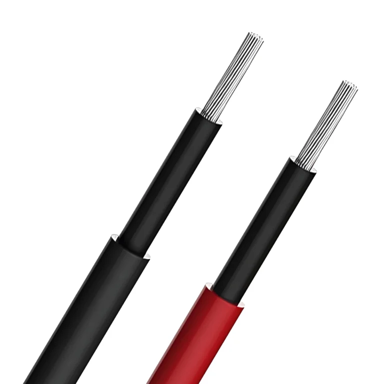
H1Z2Z2-K cable is mainly used for the connection between solar panels and between solar panels and inverters/junction boxes in PV power generation systems.
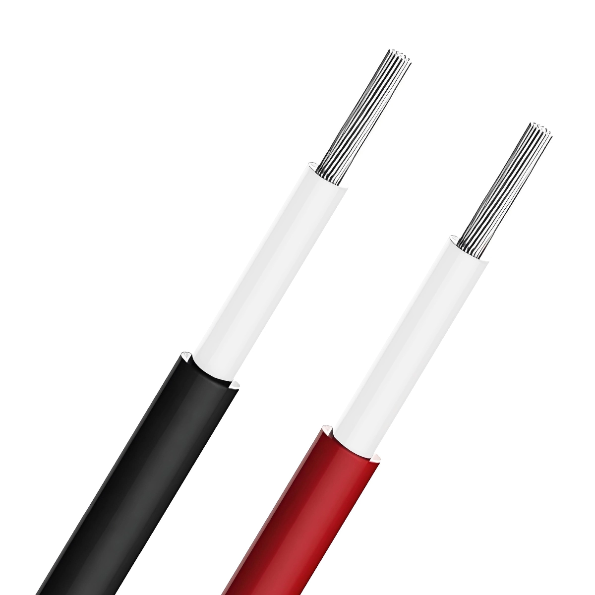
ZMS solar H1Z2Z2-K cable uses low-smoke halogen-free irradiated cross-linked polyolefin material, which can adapt to harsh outdoor weather conditions. It features resistance to humidity and heat, high and low temperatures, acids and alkalis, ozone resistance, UV resistance, flame retardancy, abrasion resistance, and strong toughness.
The solar cable H1Z2Z2-K in the ZMS photovoltaic cable series has high transmission efficiency and a long service life of up to 25 years. This type of PV cable is easy to install, safe, and reliable, and can be widely used in various solar energy engineering projects, public solar power generation, photovoltaic power plants, etc.
- Specifications: 1.5~240mm²
- Product Standard: EN50618:2014
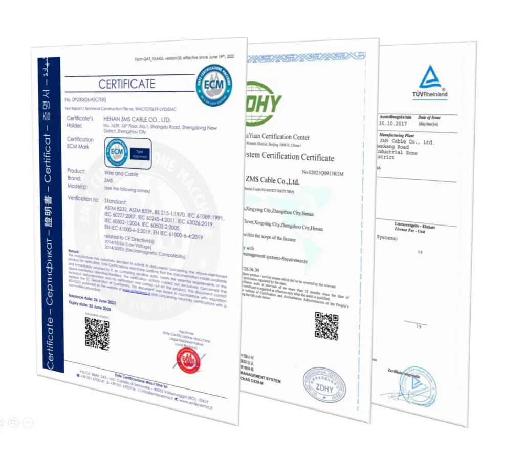
- Product Certification: TÜV, CE, ISO
H1Z2Z2-K Cable Technical Parameters
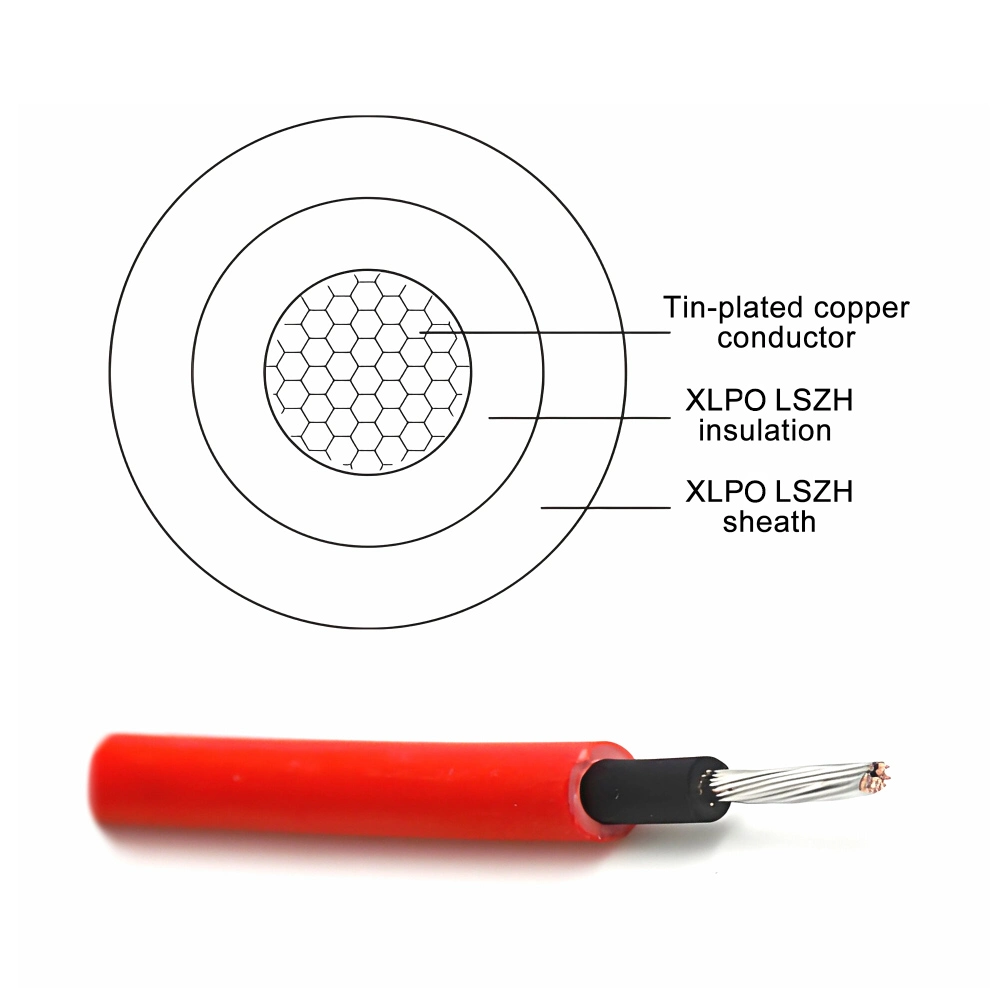
- Conductor: 99.9% Tin-plated Copper
- Insulation: Low smoke halogen-free irradiated cross-linked polyolefin (Black)
- Sheath: Low smoke halogen-free irradiated cross-linked polyolefin (Black/Red)
- AC Rated Voltage (Uo/U): 1.0/1.0kV
- DC Rated Voltage (Uo): 1.5kV (Between conductors, conductor to earth)
- Maximum System Voltage (Um): 1.2kV
- Conductor Operating Temperature: -45°C to +120°C
- Operating Ambient Temperature: -40°C to +90°C
- Cable Laying Temperature: Not lower than -25°C
- Flame Retardant Rating: EN50625 / UL1571
- Minimum Bending Radius: 6D (D: Outer diameter of the cable)
- Installation Methods: Conduit laying, shallow trench laying, cable trench laying, tunnel laying, sandwich laying, supported aerial laying, suspended aerial laying, etc.
- Service Life: ≥25 years
ZMS H1Z2Z2-K Certification
H1Z2Z2-K Cable Structure Parameters
| Specification (mm²) | Conductor Diameter (mm) | Nominal Insulation Thickness (mm) | Nominal Sheath Thickness (mm) | Approximate Cable Outside Diameter (mm) | Approximate Cable Weight (kg/km) | Maximum DC Resistance of Conductor at 20°C (Ω/km) |
| 1×1.5 | 1.58 | 0.7 | 0.8 | 4.6 | 35 | 13.7 |
| 1×2.5 | 2.02 | 0.7 | 0.8 | 5.0 | 47 | 8.21 |
| 1×4 | 2.58 | 0.7 | 0.8 | 5.6 | 65 | 5.09 |
| 1×6 | 3.17 | 0.7 | 0.8 | 6.2 | 87 | 3.39 |
| 1×10 | 4.1 | 0.7 | 0.8 | 7.6 | 132 | 1.95 |
| 1×16 | 5.6 | 0.7 | 0.9 | 8.8 | 197 | 1.24 |
| 1×25 | 7.1 | 0.9 | 1.0 | 10.9 | 303 | 0.795 |
| 1×35 | 8.5 | 0.9 | 1.1 | 12.5 | 410 | 0.565 |
| 1×50 | 10.2 | 1.0 | 1.2 | 14.6 | 573 | 0.393 |
| 1×70 | 12.0 | 1.1 | 1.2 | 16.6 | 777 | 0.277 |
| 1×95 | 14.0 | 1.1 | 1.3 | 18.8 | 1030 | 0.210 |
| 1×120 | 16.0 | 1.2 | 1.3 | 21.0 | 1284 | 0.164 |
| 1×150 | 17.0 | 1.4 | 1.4 | 22.6 | 1594 | 0.132 |
| 1×185 | 19.0 | 1.6 | 1.6 | 25.4 | 1979 | 0.108 |
| 1×240 | 22.0 | 1.7 | 1.7 | 28.8 | 2540 | 0.0817 |
H1Z2Z2-K Long-Term Allowable Current Carrying Capacity
| Installation | Single cable in air | Single cable on the surface of an object | Two cables in contact on the surface of an object |
| Cross Section (mm²) | Carrying Capacity (A) | ||
| 1.5 | 30 | 29 | 24 |
| 2.5 | 41 | 39 | 33 |
| 4 | 55 | 52 | 44 |
| 6 | 70 | 67 | 57 |
| 10 | 98 | 93 | 79 |
| 16 | 132 | 125 | 107 |
| 25 | 176 | 167 | 142 |
| 35 | 218 | 207 | 176 |
| 50 | 276 | 262 | 221 |
| 70 | 347 | 330 | 278 |
| 95 | 416 | 395 | 333 |
| 120 | 488 | 464 | 390 |
| 150 | 566 | 538 | 453 |
| 185 | 644 | 612 | 515 |
| 240 | 775 | 736 | 620 |
| Operating Temperature | 120°C | ||
| Ambient Temperature | 60°C | ||
FAQ
Why Use Special Cables for Photovoltaic Systems?
Photovoltaic cables are specifically designed for photovoltaic power generation projects, with insulation and sheathing characteristics that ordinary cables do not possess.
If ordinary cables are used in PV system, they are prone to failure in harsh outdoor environments, greatly reducing the lifespan of the entire solar power system. Additionally, it can lead to current overload, severe voltage drop, frequent generation faults, and low generation efficiency in photovoltaic power plants, even potentially causing fires in the plant.
Therefore, to ensure the long-term stable operation of photovoltaic power plants for 25 years, it is essential to choose cables specifically designed for photovoltaic systems, such as H1Z2Z2-K or PV1-F.
What Specifications Should Be Chosen for H1Z2Z2-K PV Cables?
In typical photovoltaic systems, the most common options are H1Z2Z2-K 1×4 and H1Z2Z2-K 1×6 cables. Generally, larger cable cross-sections indicate greater load-bearing capacities.
Considerations such as working voltage, current capacity, and environmental temperature range should also be factored in. After determining the voltage and current requirements, refer to the parameter table of H1Z2Z2-K cables to select the appropriate specification.
If you encounter uncertainty in selecting cable specifications, our ZMS technical team is available to offer tailored solutions.
What Are the Differences Between H1Z2Z2-K and PV1-F Photovoltaic Cables?
PV1-F cable is an older version solar cable that complies with the TÜV 2Pfg1169 standard, and its standard certification has ceased updating. In contrast, the H1Z2Z2-K photovoltaic cable complies with the latest TÜV EN50618:2014 certification.
The voltage ratings differ between PV1-F and H1Z2Z2-K cables. PV1-F has a voltage rating of DC: 1.0kV and AC: Uo/U: 0.6/1.0kV, while H1Z2Z2-K has a voltage rating of DC: 1.5kV and AC: Uo/U: 1.0/1.0kV. H1Z2Z2-K can provide higher transmission efficiency and stability.
In terms of structure, PV1-F cable has a single insulation layer, whereas H1Z2Z2-K cable adopts a dual-layer insulation structure. This make H1Z2Z2-K cable superior in durability and protection, especially against mechanical damage and environmental factors.
In summary, H1Z2Z2-K solar cable is more advanced in design, offering higher electrical and mechanical performance, suitable for more demanding application environments. On the other hand, PV1-F solar cable is primarily advantageous in cost-effectiveness, suitable for most conventional photovoltaic systems.
For cost-effectiveness considerations, PV1-F cable can be used for series connections between photovoltaic modules and parallel connections from strings to DC distribution boxes. Meanwhile, H1Z2Z2-K cable can be used for connections between distribution boxes and inverters, as well as for direct current connections in large inverters.
What Are the Differences Between DC and AC Applications of H1Z2Z2-K Photovoltaic Cables?
H1Z2Z2-K cables can be used for both DC circuits (1.5kV) and AC circuits (1.0/1.0kV). In photovoltaic power generation systems, their specific application differences are as follows:
For DC Applications:
- Series connection between photovoltaic modules
- Parallel connection between strings
- Parallel connection from strings to DC distribution boxes
- Connection from DC distribution boxes to inverters
For AC Applications:
- Connection from inverters to step-up transformers
- Connection from step-up transformers to distribution devices
- Connection from distribution devices to the grid or users
Why Are Solar Cables Split into Red and Black?
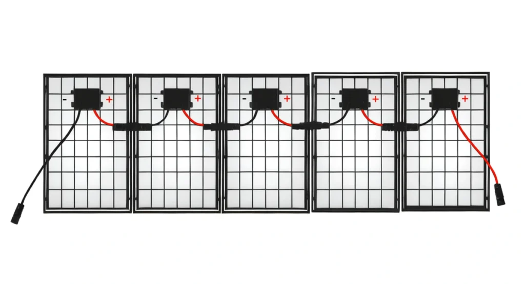
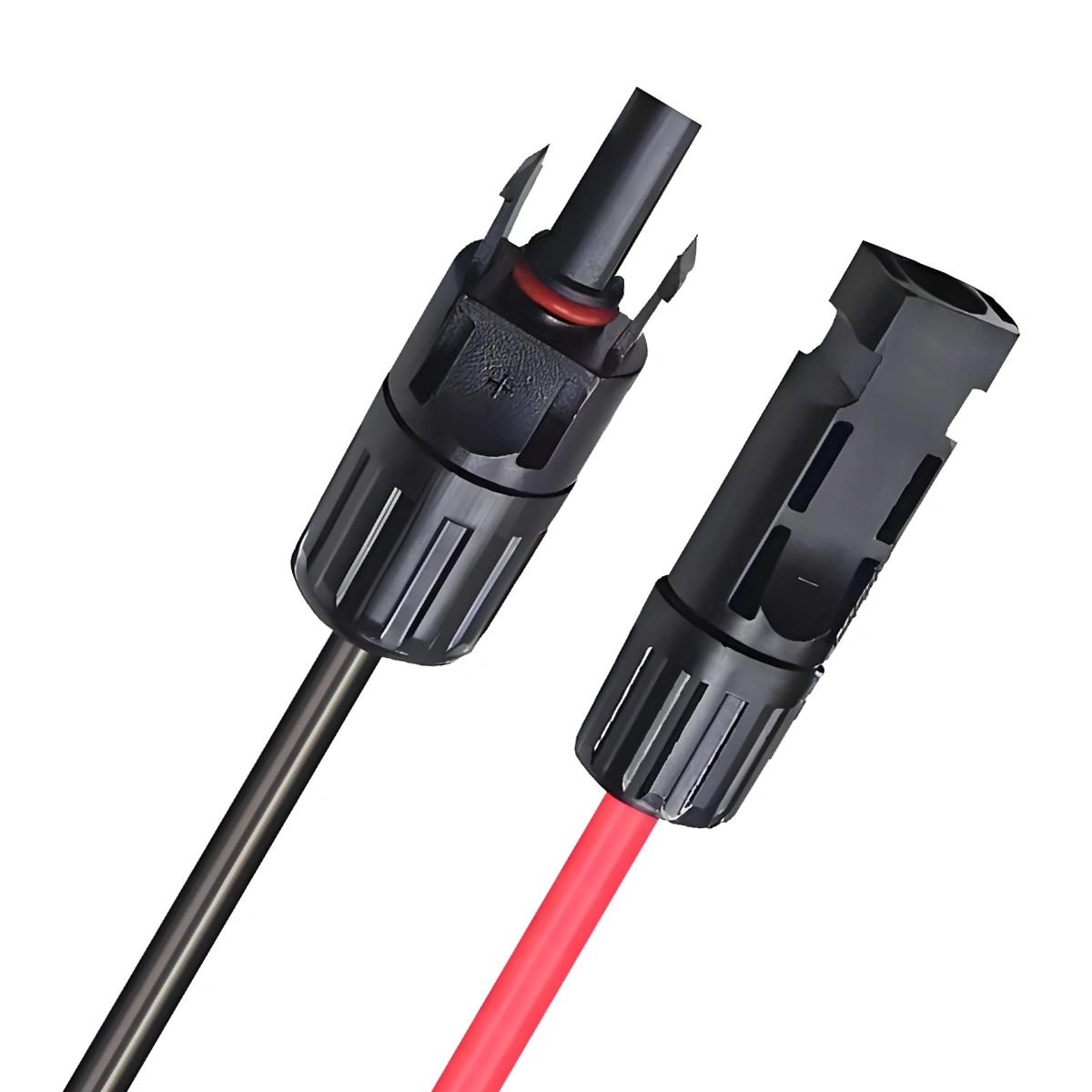
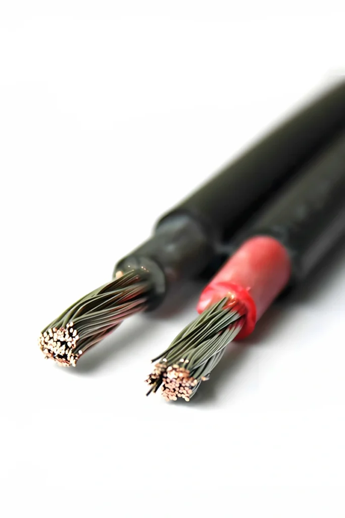
In the photovoltaic industry, using red and black cables has become a widely accepted method of identification. Their primary purpose is to distinguish between positive and negative poles. In DC circuits, typically, red solar wires indicate the positive pole of the current, while black solar wires indicate the negative pole. This color differentiation helps quickly identify the polarity of photovoltaic connections during the installation and maintenance of solar systems, thus preventing wiring errors.
How to Make Solar Panel Connectors and Connect Solar Panels with H1Z2Z2-K Cables?
Once the solar connectors are prepared, solar panels can be connected in parallel, series, or hybrid configurations.
In parallel connection, the positive and negative terminals of multiple photovoltaic panels are connected separately. This cabling method increases the overall current output of the system, suitable for scenarios requiring higher current output.
In series connection, the positive and negative terminals of multiple photovoltaic panels are connected sequentially. This cabling method increases the overall voltage output of the system, suitable for scenarios requiring higher voltage output.
Hybrid connection combines parallel and series wiring methods. It involves connecting some photovoltaic panels in parallel and then connecting these parallel combinations in series. Hybrid wiring methods allow flexible combinations to meet the energy needs of different scenarios.
ZMS can provide various universal MC connectors separately, which are perfectly compatible with MC4 connectors. Additionally, we can also provide solar panel extension cables with pre-made connectors to meet your different requirements.
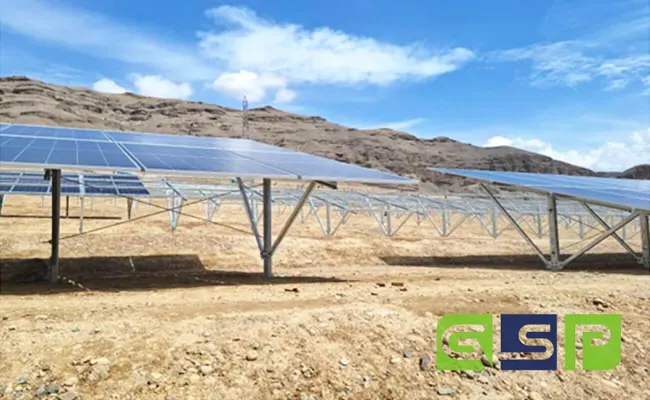
Project Highlight
ZMS joined forces with Green State Power (GSP), a pioneer in renewable energy infrastructure, to equip a monumental 10 MWP photovoltaic project in Kabul, Afghanistan.
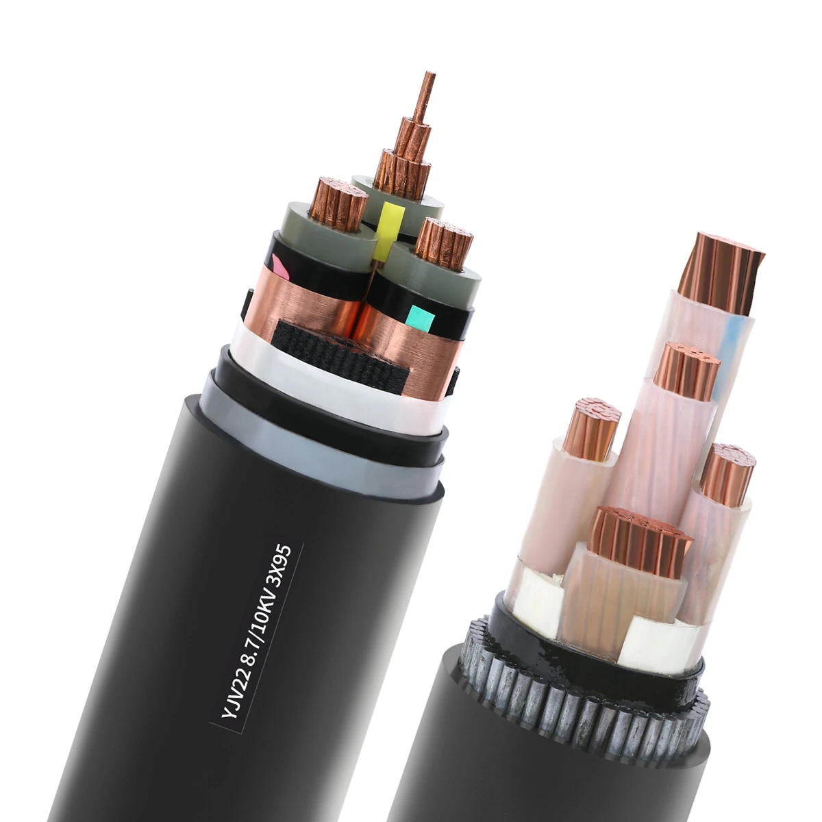
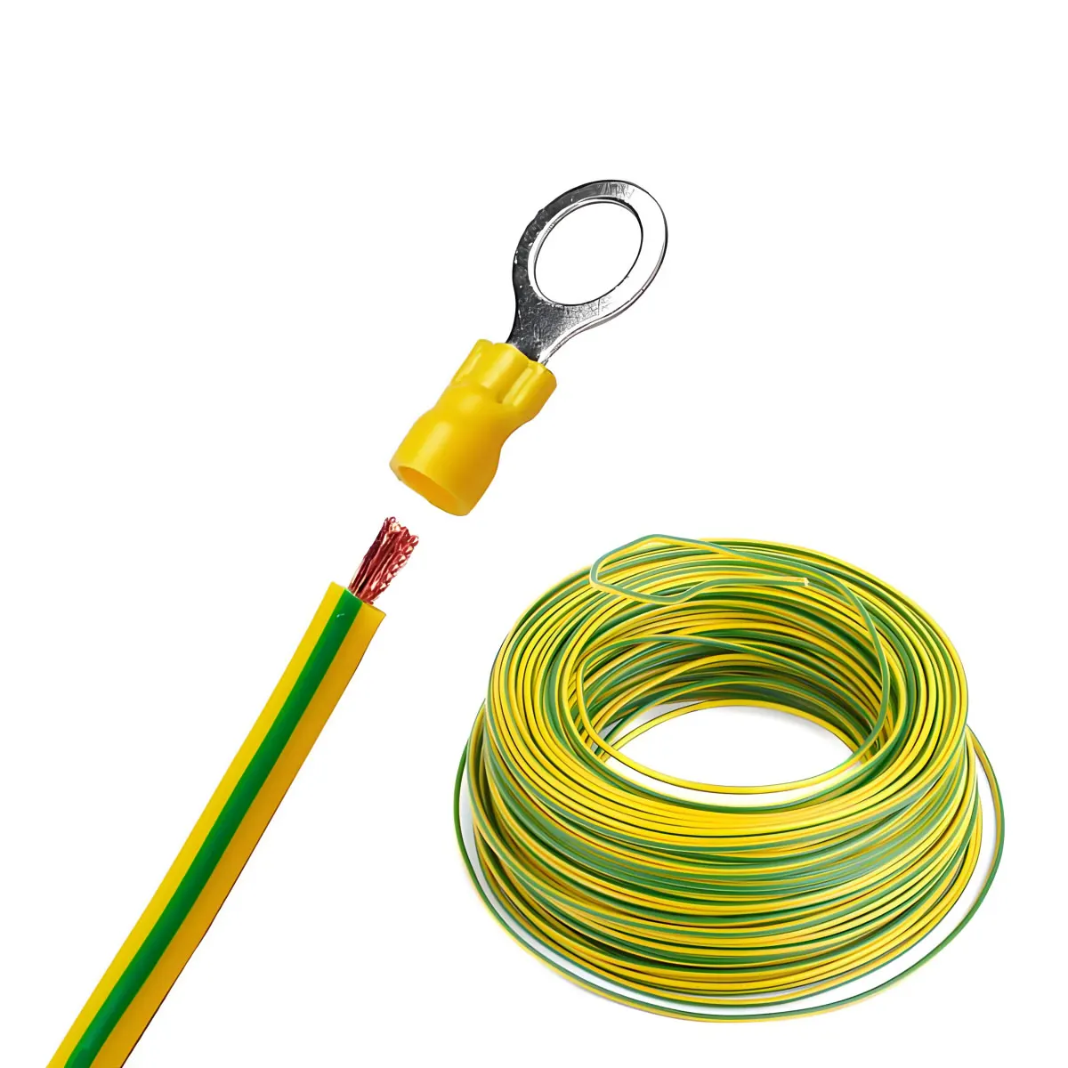
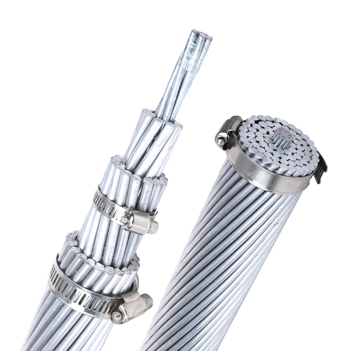
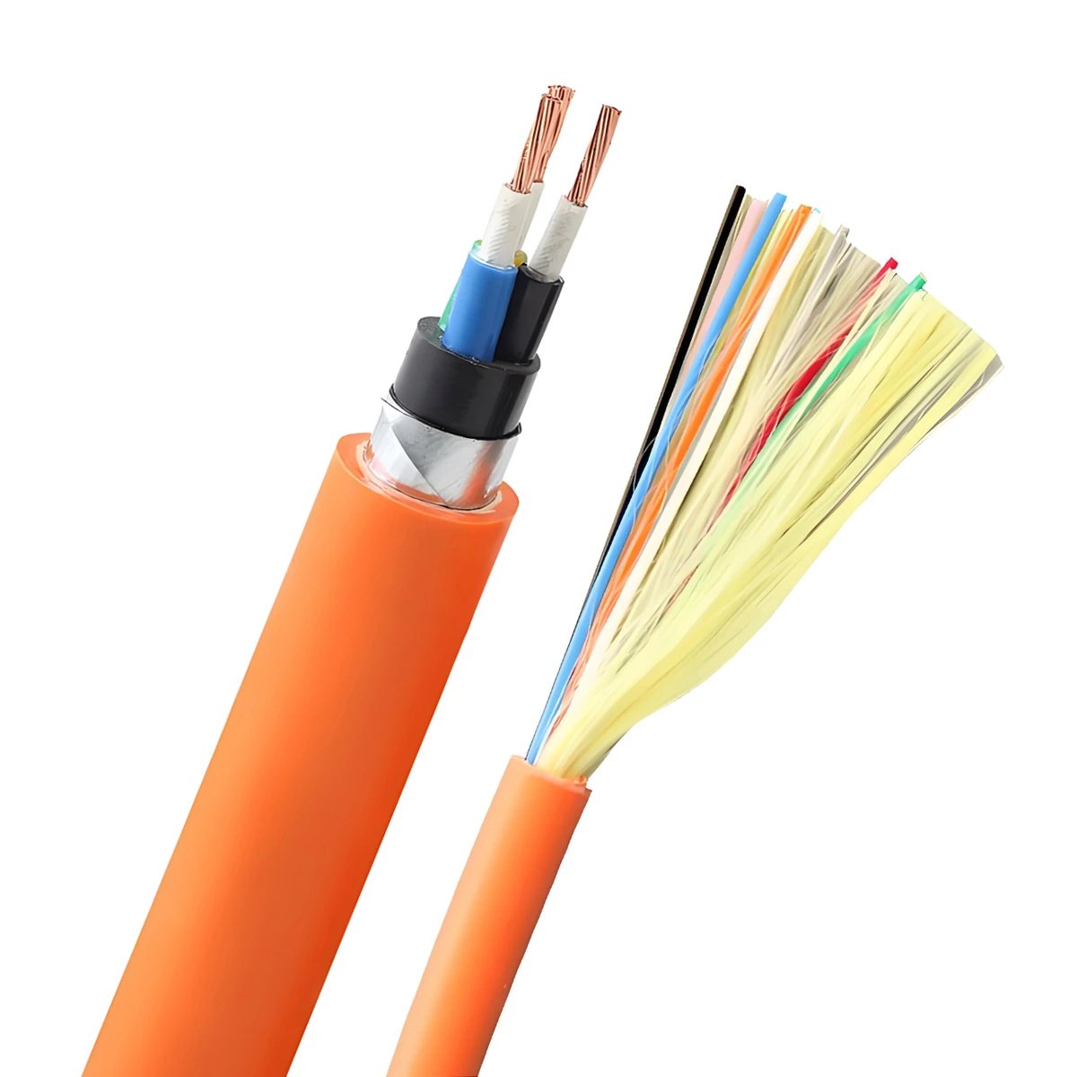
ZMS comprehensively analyzed the PV project and provided it with 1X10 and 1X6 solar cables H1Z2Z2-K, 3X300 LV cables, 3X300 MV cables, as well as ACSR 185/30 overhead cables. Complementing these were vital accessories like PV connectors and meticulously curated toolboxes.
ZMS’s commitment to quality and reliability facilitated smooth installation and operational efficiency, contributing to the region’s sustainable energy infrastructure.
ZMS Service
Customized Manufacturing
We understand that every customer's needs are unique. Therefore, we offer personalized solar cable customization services, tailoring every detail from cable specifications to connection interfaces according to your specific project requirements, ensuring maximum compatibility and efficiency.
Global Rapid Response Logistics
With the support of our global logistics network, ZMS ensures that your photovoltaic cable orders reach any corner of the world safely and promptly. Our professional logistics team monitors every stage of transportation to ensure timely delivery of your goods.
Technical Support
ZMS's technical support team is always on standby. Whatever technical challenges you encounter, we can provide rapid responses and professional solutions, ensuring a worry-free user experience.
Green Production
Our solar cables and accessories strictly adhere to environmental standards during the production process, minimizing their impact on the environment. By choosing ZMS, you are not only investing in high-quality photovoltaic cables but also contributing to the sustainable development of the planet.

