
À medida que o mundo muda para energias renováveis, a energia solar emergiu como uma das fontes de eletricidade mais populares e sustentáveis. Projetos solares, seja residencial ou comercial, requerem planejamento cuidadoso e consideração, especialmente quando se trata de selecionar os componentes certos. Entre esses componentes, cabos desempenham um papel crítico para garantir a eficiência, segurança, e longevidade do sistema de energia solar.
Índice
- Processo de geração de energia do sistema solar
- Que tipos de cabos são necessários para sistemas de energia solar?
- Qual a porcentagem do custo total de construção, os cabos representam em uma usina fotovoltaica?
- Sobre cabos solares DC
- Por que usar cabos especiais para sistemas fotovoltaicos?
- O que é a certificação TÜV para cabos solares?
- Quais especificações devem ser escolhidas para os cabos PV H1Z2Z2-K?
- Quais são as diferenças entre as aplicações DC e CA de cabos fotovoltaicos H1Z2Z2-K?
- Quais são as diferenças entre os cabos fotovoltaicos H1Z2Z2-K e PV1-F?
- Como selecionar a especificação do cabo PV1-F?
- Por que os cabos solares são divididos em vermelho e preto?
- Você pode fazer conectores de cabo solar sozinho?
- Quais são os conectores solares comumente usados?
- Sobre cabos solares AC
- Sobre Cabos para Sistema de Aterramento
- Por que os sistemas de geração de energia solar devem ser aterrados?
- Que aterramento é necessário em sistemas de energia solar?
- Como os painéis solares são aterrados?
- Por que as estruturas dos painéis solares devem ser conectadas e aterradas?
- Qual material deve ser usado para haste de aterramento em sistemas fotovoltaicos?
- Quais especificações das barras de terra são comumente usadas?
- Como as hastes de terra devem ser instaladas em sistemas fotovoltaicos?
- Cabos aéreos, Cabos de controle e cabos de comunicação em projetos fotovoltaicos
- Requisitos legais e regulamentares para roteamento de cabos em projetos solares
- Melhores práticas para roteamento de cabos
- Conselhos essenciais para comprar cabos
- Considerações Finais
Selecionar os cabos apropriados para o seu projeto solar pode ser uma tarefa difícil, dada a variedade de opções disponíveis e os requisitos específicos da energia fotovoltaica (PV) sistemas. Este guia tem como objetivo fornecer uma visão abrangente de tudo o que você precisa saber sobre a compra de cabos para o seu projeto solar.. Desde a compreensão do processo de geração de energia solar até a seleção dos tipos certos de cabos para diferentes aplicações, cobriremos todos os aspectos essenciais para ajudá-lo a tomar decisões informadas.
Ao final deste guia, você terá uma compreensão clara dos fatores críticos a serem considerados ao comprar cabos para o seu projeto solar, garantindo que seu sistema opere de forma eficiente e segura nos próximos anos.
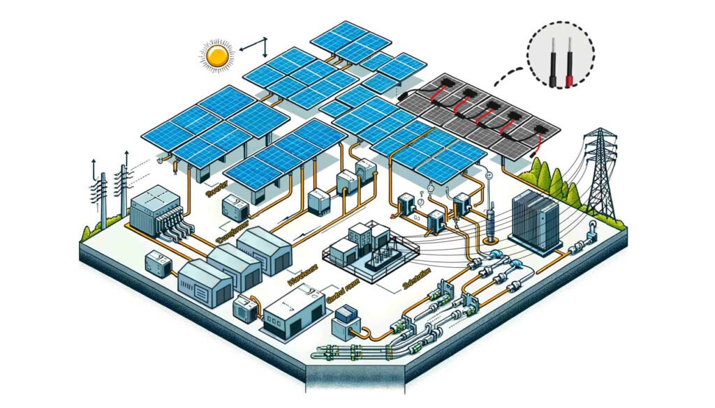
Processo de geração de energia do sistema solar
Compreender os processos de geração de energia do sistema solar é crucial para selecionar os cabos e componentes certos para o seu projeto fotovoltaico. A seleção adequada do cabo garante a transmissão eficiente e segura de eletricidade em todo o sistema, seja uma configuração conectada à rede ou fora da rede.
1. Painéis solares capturam a luz solar
Painéis solares, composto por numerosas células solares, capturar a luz solar quando os fótons (partículas de luz) atingir a superfície. Esses fótons transferem sua energia para os elétrons dentro das células solares, criando uma corrente elétrica.
2. Geração de Eletricidade
A energia dos fótons energiza os elétrons, fazendo com que eles fluam e produzam uma corrente contínua (CC). Os painéis solares são normalmente dispostos em grandes conjuntos para gerar quantidades significativas de eletricidade, suficiente para abastecer casas, negócios, ou comunidades inteiras.
3. Conversão de Inversor
A eletricidade DC gerada pelos painéis solares não pode ser usada diretamente pela maioria dos eletrodomésticos e equipamentos comerciais, que operam em corrente alternada (AC). Para preencher essa lacuna, um inversor é usado para converter a eletricidade DC em eletricidade AC, tornando-o compatível com sistemas elétricos padrão.
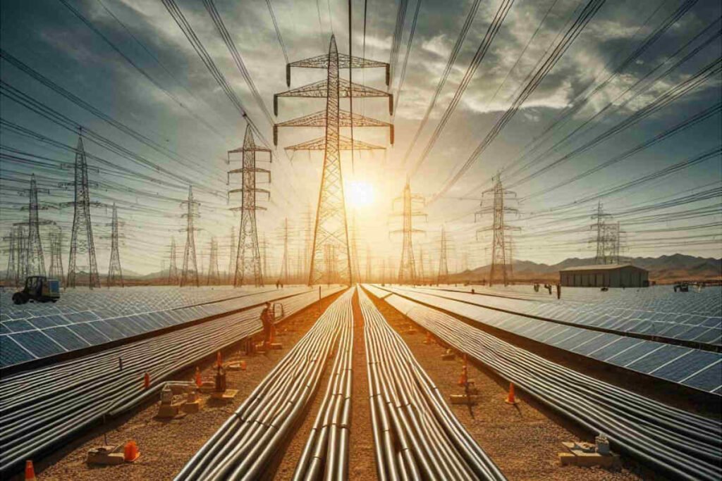
4. Transmissão e Distribuição
Após a conversão para AC, a eletricidade é enviada para um transformador. O transformador aumenta a tensão da eletricidade, o que permite que seja transmitido de forma eficiente por longas distâncias através de linhas de energia. A energia CA de alta tensão é então distribuída pela rede para vários consumidores, incluindo residências e empresas.
Sistemas conectados à rede
Em sistemas conectados à rede, o processo é o seguinte:
- Painéis fotovoltaicos geram energia CC: Painéis solares capturam a luz solar e geram energia DC.
- Inversor converte em energia CA: A energia DC é convertida em energia AC pelo inversor.
- Transformador aumenta tensão: Se necessário, um transformador aumenta a tensão para uma transmissão eficiente.
- Transmissão para a rede: A energia CA é transmitida através de linhas aéreas para a rede.
Neste sistema, a energia elétrica é convertida entre CC e CA apenas uma vez no estágio do inversor. Após a conversão, a eletricidade é transmitida e usada na forma AC.
Sistemas fora da rede
Em sistemas fora da rede, o processo é um pouco diferente:
- Painéis fotovoltaicos geram energia CC: Painéis solares capturam a luz solar e geram energia DC.
- Inversor converte em energia CA: A energia DC é convertida em energia AC pelo inversor.
- Transformador aumenta tensão: Se necessário, um transformador aumenta a tensão.
- Uso direto ou armazenamento: A energia CA pode ser conectada diretamente à rede do usuário para uso imediato ou armazenada em baterias para uso posterior.
Os sistemas fora da rede dependem do armazenamento de baterias para garantir um fornecimento contínuo de energia, mesmo quando a luz solar não está disponível, como durante a noite ou dias nublados.
Depois de conhecer o processo de geração de energia solar, podemos determinar quais cabos são necessários para todo o sistema.
Que tipos de cabos são necessários para sistemas de energia solar?
Como um componente crucial das soluções de energia sustentável, A operação segura e eficiente dos sistemas de geração de energia solar depende da configuração e uso apropriados de vários cabos especializados. Os tipos de cabos necessários em um sistema de geração de energia solar incluem o seguinte:
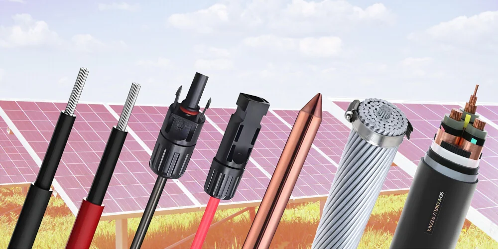
Cabo Solar DC
Esses cabos são projetados especificamente para conectar módulos fotovoltaicos (painéis solares) e para transmissão de energia entre os módulos para a caixa de combinadores DC. Dada a exposição direta a ambientes externos, Eles devem possuir as seguintes características:
- Resistência a UV: Para impedir a degradação do desempenho devido à exposição ao sol prolongado.
- Resistência ao tempo: Para suportar várias condições climáticas, incluindo temperaturas extremas, umidade, e areia soprada pelo vento.
- Resistência à corrosão por spray de sal: Adequado para áreas costeiras para evitar danos causados pelo sal.
- Retardância da chama: Para reduzir os riscos de incêndio e aumentar a segurança do sistema.
- Força mecânica: Para suportar a instalação e as pressões ambientais sem ser facilmente danificado.
Cabo CA
Os cabos CA são usados na extremidade do inversor para transmitir a energia CA convertida para a placa de distribuição CA ou diretamente para a grade. Esses cabos precisam atender aos padrões de conexão da grade e possuir boas propriedades de isolamento e resistência ao calor para garantir uma transmissão de energia segura e eficiente.
Cabo de comunicação de dados
Em um sistema de geração de energia solar, Os cabos de comunicação de dados atuam como a ponte de informação. Eles não apenas transmitem os dados elétricos gerados pela matriz fotovoltaica, mas também transmitem informações de status em tempo real de inversores e outros equipamentos de monitoramento para o sistema de monitoramento central por meio de redes com fio ou sem fio (incluindo fibra óptica) para otimização do sistema e diagnóstico de falhas.
Cabo de controle
Os cabos de controle são usados para conectar controladores, inversores, e outros equipamentos auxiliares dentro do sistema, garantir controle automatizado e monitoramento eficaz. Esses cabos precisam ter uma boa estabilidade de transmissão de sinal e recursos anti-interferência para garantir a execução precisa dos comandos de controle.
Cabo de aterramento
Os cabos de aterramento desempenham um papel crítico na proteção de segurança de todo o sistema de geração de energia solar. Eles fornecem um caminho de baixa resistência para descarregar correntes de raio ou correntes de falha do sistema, Prevenção de choques elétricos e danos ao equipamento, garantindo assim a segurança do pessoal e do equipamento.
Cabo aéreo
Em determinados cenários de instalação, como transmissão de longa distância ou restrições de terreno, Os cabos aéreos são usados para a conexão da grade do sistema de geração de energia solar. Esses cabos precisam ser especialmente projetados para resistir a danos físicos externos e fatores climáticos, mantendo boa condutividade e força mecânica.
Ao selecionar esses cabos solares, É essencial não apenas considerar suas características e ambientes aplicáveis, mas também garantir que todos os cabos e acessórios cumpram os padrões locais de segurança elétrica e os regulamentos da indústria para garantir a operação estável a longo prazo e a conformidade do sistema de geração de energia solar.
Qual a porcentagem do custo total de construção, os cabos representam em uma usina fotovoltaica?
O custo dos cabos em um fotovoltaico (PV) a usina de energia normalmente representa ao redor 10% do custo total de construção. Essa porcentagem pode variar com base em vários fatores, como a escala do projeto, Seleção de equipamentos, diferenças regionais, e flutuações de mercado. De acordo com algumas estimativas:
- Módulos fotovoltaicos (painéis solares) conta aproximadamente 50% do custo total do equipamento.
- Inversores e outros equipamentos elétricos representam cerca de 10%.
- Cabos e estruturas de montagem 10%.
Portanto, Os custos de cabo geralmente compõem sobre 10% do custo total de construção. No entanto, Esta é uma estimativa aproximada, e a proporção real pode variar dependendo do orçamento específico e dos preços materiais de um projeto. Adicionalmente, com avanços em tecnologia e mudanças de mercado, Essa porcentagem pode estar sujeita a ajustes.
Sobre cabos solares DC
Por que usar cabos especiais para sistemas fotovoltaicos?
Os cabos fotovoltaicos são projetados especificamente para projetos de geração de energia fotovoltaica, com características de isolamento e revestimento que os cabos comuns não possuem.
Se os cabos comuns forem usados no sistema fotovoltaico, Eles são propensos ao fracasso em ambientes externos severos, reduzindo bastante a vida útil de todo o sistema de energia solar. Adicionalmente, pode levar à sobrecarga atual, queda grave de tensão, Falhas de geração frequente, e eficiência de baixa geração em usinas fotovoltaicas, até potencialmente causar incêndios na planta.
Portanto, para garantir a operação estável de longo prazo de usinas fotovoltaicas para 25 anos, É essencial escolher cabos projetados especificamente para sistemas fotovoltaicos, como H1Z2Z2-K ou PV1-F.
O que é a certificação TÜV para cabos solares?
A Certificação de Cabo Solar TÜV refere-se a uma série de certificados concedidos a cabos que foram testados, inspecionado e certificado por um terceiro independente do Grupo TÜV Rheinland, com sede na Alemanha, de acordo com normas específicas.
Como um tipo especial de cabo, a segurança e o desempenho dos cabos fotovoltaicos são cruciais para os sistemas de geração de energia solar, portanto, eles passam por testes e certificação rigorosos para garantir sua qualidade e confiabilidade.
Em relação à certificação TÜV para cabos fotovoltaicos, seu desenvolvimento progrediu desde o 2PfG 1169/08.2007 padrão para EN 50618:2014 padrão. O padrão mais recente é IEC FDIS 62930, mas a maioria das certificações de cabos solares ainda aderem à EN válida 50618 padrão.
Quais especificações devem ser escolhidas para os cabos PV H1Z2Z2-K?
Em sistemas fotovoltaicos típicos, As opções mais comuns são H1Z2Z2-K 1×4 e H1Z2Z2-K 1×6 cabos. Geralmente, Seções transversais maiores indicam maiores capacidades de carga.
Considerações como tensão de trabalho, Capacidade atual, e a faixa de temperatura ambiental também deve ser fatorada em. Depois de determinar a tensão e os requisitos atuais, Consulte a tabela de parâmetros dos cabos H1Z2Z2-K para selecionar a especificação apropriada.
Se você encontrar incerteza na seleção de especificações do cabo, Nossa equipe técnica do ZMS está disponível para oferecer soluções personalizadas.
Saiba mais sobre Cabo solar H1Z2Z2-K
Quais são as diferenças entre as aplicações DC e CA de cabos fotovoltaicos H1Z2Z2-K?
Os cabos H1Z2Z2-K podem ser usados para ambos os circuitos CC (1.5kV) e circuitos CA. (1.0/1.0kV). Em sistemas de geração de energia fotovoltaica, Suas diferenças específicas de aplicação são as seguintes:
Para aplicativos DC:
- Conexão em série entre módulos fotovoltaicos
- Conexão paralela entre seqüências
- Conexão paralela de cordas para caixas de distribuição DC
- Conexão de caixas de distribuição DC para inversores
Para aplicações CA.:
- Conexão de inversores para transformadores de intensificação
- Conexão de transformadores de intensificação para dispositivos de distribuição
- Conexão de dispositivos de distribuição para a grade ou usuários
Quais são as diferenças entre os cabos fotovoltaicos H1Z2Z2-K e PV1-F?
O cabo PV1-F é uma versão mais antiga do cabo solar que está em conformidade com o padrão TÜV 2Pfg1169, e sua certificação padrão deixou de ser atualizada. Em contraste, o cabo fotovoltaico H1Z2Z2-K está em conformidade com a mais recente TÜV EN50618:2014 certificação.
As classificações de tensão diferem entre os cabos PV1-F e H1Z2Z2-K. PV1-F tem uma tensão nominal de CC: 1.0kV e CA: Uo/U: 0.6/1.0kV, enquanto H1Z2Z2-K tem uma tensão nominal de DC: 1.5kV e CA: Uo/U: 1.0/1.0kV. H1Z2Z2-K pode fornecer maior eficiência e estabilidade de transmissão.
Em termos de estrutura, O cabo PV1-F possui uma única camada de isolamento, enquanto o cabo H1Z2Z2-K adota uma estrutura de isolamento de camada dupla. Isso torna o cabo H1Z2Z2-K superior em durabilidade e proteção, especialmente contra danos mecânicos e fatores ambientais.
Resumindo, O cabo solar H1Z2Z2-K tem design mais avançado, oferecendo maior desempenho elétrico e mecânico, adequado para ambientes de aplicação mais exigentes. Por outro lado, O cabo solar PV1-F é principalmente vantajoso em termos de custo-benefício, adequado para a maioria dos sistemas fotovoltaicos convencionais.
Para considerações de custo-benefício, O cabo PV1-F pode ser usado para conexões em série entre módulos fotovoltaicos e conexões paralelas de strings a caixas de distribuição CC. Enquanto isso, O cabo H1Z2Z2-K pode ser usado para conexões entre caixas de distribuição e inversores, bem como para conexões de corrente contínua em grandes inversores.
Como selecionar a especificação do cabo PV1-F?
Atualmente, o cabo DC fotovoltaico mais comumente usado é o PV1-F 1×4 cabo. No entanto, com o aumento das correntes do módulo fotovoltaico e da potência do inversor único, a aplicação de PV1-F 1×6 Os cabos DC também estão aumentando.
De acordo com especificações relevantes, é geralmente recomendado que a perda de linhas de energia CC fotovoltaicas não exceda 2%. Em circuitos CC, a resistência da linha do cabo PV1-F 1x4mm² é 4,6mΩ/m, e a resistência da linha do cabo PV1-F 1x6mm² é 3,1mΩ/m. Assumindo uma tensão de trabalho de 600 V para módulos DC, um 2% perda de queda de tensão é 12V. Assumindo uma corrente de módulo de 13A, ao usar cabo DC de 4 mm², a distância máxima recomendada da extremidade mais distante do módulo ao inversor não deve exceder 120 metros (corda única, excluindo pólos positivos e negativos). Se ultrapassar essa distância, recomenda-se escolher um cabo DC de 6 mm², mas a distância máxima recomendada da extremidade mais distante do módulo ao inversor não deve exceder 170 metros.
Para reduzir custos do sistema, usinas fotovoltaicas agora raramente configuram módulos e inversores em um 1:1 razão. Em vez de, eles projetam uma certa quantidade de excesso de capacidade com base em fatores como condições de luz solar e requisitos do projeto. Por exemplo, para um módulo de 110KW, um inversor de 100KW é selecionado, e é calculado com base em uma sobrecapacidade de 1,1x no lado CA do inversor. A corrente máxima de saída CA é de aproximadamente 158A. Os cabos CA são selecionados com base na corrente de saída máxima do inversor. Porque independentemente de quanto os módulos estejam superconfigurados, a corrente de entrada CA do inversor nunca excederá a corrente máxima de saída do inversor.
Saiba mais sobre Cabo solar PV1-F
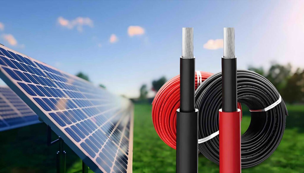
Por que os cabos solares são divididos em vermelho e preto?
Na indústria fotovoltaica, O uso de cabos vermelhos e pretos tornou -se um método de identificação amplamente aceito. Seu objetivo principal é distinguir entre postes positivos e negativos. Em circuitos CC, tipicamente, Os fios solares vermelhos indicam o pólo positivo da corrente, Enquanto os fios solares pretos indicam o poste negativo. Essa diferenciação de cores ajuda a identificar rapidamente a polaridade das conexões fotovoltaicas durante a instalação e manutenção de sistemas solares, impedindo assim erros de fiação.
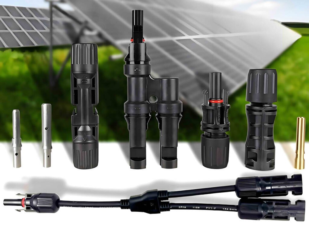
Você pode fazer conectores de cabo solar sozinho?
O processo de fabricação de conectores de cabos solares inclui verificação de danos a núcleos e cabeças masculinos e femininos, e usando strippers de arame, ferramentas de crimpagem, e chaves abertas. Até os não profissionais podem fazer esses conectores seguindo etapas específicas.
Comparado a fazer conectores você mesmo, Cabos de extensão de painel solar diretamente personalizados podem ser um pouco mais caros, Mas pode economizar tempo e trabalho e tornar a instalação mais conveniente.
Quais são os conectores solares comumente usados?
O tipo de conector mais usado em sistemas fotovoltaicos solares é o conector MC4. Tornou -se um dos padrões para conectores fotovoltaicos devido ao seu uso generalizado e reconhecimento de mercado. Os cabos de extensão do conector MC4 podem suportar alta tensão e corrente e são adequados para conectar painéis solares, inversores, e outros componentes do sistema.
Os conectores compatíveis com MC4 do ZMS são consistentes com os conectores MC4 em especificações, tamanho, e tolerância e pode ser 100% combinado.
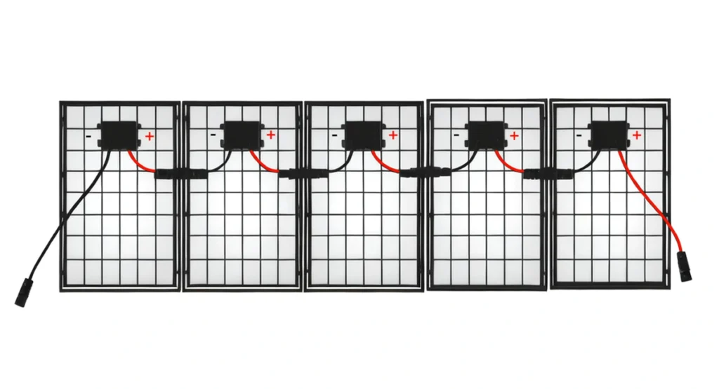
Além dos conectores MC4, Outros conectores solares comumente usados incluem conectores do tipo Y ou paralelos. A estrutura deles é um conector um para muitos, que podem conectar vários painéis solares em série para aumentar a tensão de toda a matriz do painel, mantendo a constante atual.
Saiba mais sobre Conector de cabo solar
Sobre cabos solares AC
Como os cabos AC LV devem ser selecionados para projetos de energia solar?
Quando uma estação de energia solar está próxima do centro de carga ou é ela própria uma geração distribuída, você só precisa usar cabos de baixa tensão para conectar diretamente a uma rede de distribuição de baixa tensão trifásica de 400 V ou monofásica de 230 V. Para conectar a uma rede de média ou alta tensão, cabos de baixa tensão devem primeiro ser usados para conectar a um transformador.
A saída de tensão CA do inversor geralmente vem em vários padrões. Por exemplo, a tensão de saída de um inversor central pode ser 315V, 360V, 400V, e assim por diante, enquanto a tensão de saída de um inversor string pode ser 480V, 500V, 540V, 800V, e assim por diante.
Portanto, em sistemas fotovoltaicos, geralmente é possível usar cabos de baixa tensão com tensão nominal de 450/750V, 0.6/1 kV, ou 1.8/3 kV. Dependendo se o cabo está enterrado ou não, uma camada blindada pode ser adicionada.
Saiba mais sobre Cabo solar CA
Como os cabos AC MT devem ser selecionados para projetos de energia solar?
Se um sistema de geração de energia fotovoltaica precisar ser conectado a uma rede de média ou alta tensão, cabos de baixa tensão devem primeiro ser usados para conectar a um transformador, que aumentará a tensão para o nível apropriado. Cabos de média tensão são então usados para fornecer energia à subestação. O número de cabos de média tensão necessários depende do método de conexão.
Estrutura Estelar Tradicional
Na estrutura estelar tradicional, cada transformador possui uma única linha de saída de média tensão conectada à subestação. Esta estrutura é a mais simples e direta, e é comumente usado no projeto de usinas fotovoltaicas. Cada cabo transporta apenas a energia de um único transformador, então as especificações do cabo são menores, reduzindo custos. No entanto, já que cada transformador possui apenas uma linha conectando-se à subestação, a confiabilidade não é muito alta.
Estrutura de anel de saída única
A estrutura em anel de saída única conecta vários transformadores em um anel usando cabos, e o transformador mais próximo da subestação é conectado à subestação por meio de cabos de média tensão. Comparado com a estrutura de anel de saída dupla, a estrutura em anel de saída única usa menos cabos solares CA de média tensão. No entanto, porque todo o anel possui apenas uma linha conectando-se à subestação, a confiabilidade é menor.
Estrutura de anel de saída dupla
A estrutura em anel de saída dupla possui uma linha adicional conectando o anel à subestação em comparação com a estrutura em anel de saída única. Se uma linha de saída falhar, a outra linha pode continuar a permitir que os inversores no anel forneçam energia para a rede. Semelhante à estrutura em anel de saída única, considerando a direção do fluxo durante uma falta, todos os cabos devem ser selecionados para suportar a potência de todos os transformadores, resultando em custos relativamente mais elevados.
Estrutura da Ponte
Antes da estrutura do anel ser proposta, a estrutura da ponte era frequentemente usada. Nesta estrutura, baseado na estrutura estelar, cada par de transformadores adjacentes é conectado usando cabos de média tensão. Por aqui, cada transformador possui duas linhas conectando-se à subestação, melhorando significativamente a confiabilidade do sistema. No entanto, o custo é relativamente alto devido aos cabos adicionais entre cada par de transformadores.
Para centrais fotovoltaicas de diferentes tamanhos, a análise da seleção do cabo varia de acordo com diferentes requisitos. Ao selecionar cabos de média tensão, é essencial considerar de forma abrangente os requisitos obrigatórios, custos, e benefícios para determinar a solução e decisão mais vantajosa.
Quais são os princípios para a seleção de cabos CA para sistemas de energia solar?
A seleção de cabos CA para projetos solares segue os requisitos gerais para seleção de cabos, que incluem considerar os níveis de tensão, corrente operacional contínua, estabilidade térmica de curto-circuito, queda de tensão permitida, densidade atual econômica, e condições do ambiente de instalação. Adicionalmente, a geração de energia fotovoltaica tem características próprias, exigindo consideração para cabos que podem ser usados em condições ambientais adversas, como altas temperaturas, frio intenso, e radiação ultravioleta. Portanto, os seguintes fatores devem ser levados em consideração:
- Desempenho de isolamento do cabo
- Resistência ao calor e retardamento de chama do cabo
- Resistência à umidade e proteção UV do cabo
- Métodos de instalação do cabo
- Tipo de condutor de cabo
- Especificações do cabo
Sobre Cabos para Sistema de Aterramento
Por que os sistemas de geração de energia solar devem ser aterrados?
O aterramento em sistemas fotovoltaicos é um dos problemas mais frequentemente negligenciados pelo pessoal de instalação fotovoltaica., especialmente em sistemas fotovoltaicos de pequena capacidade, onde o aterramento e a proteção contra raios não recebem muita atenção.
No entanto, se o aterramento não for feito, erros podem ocorrer devido à baixa resistência de isolamento ao terra ou correntes de fuga excessivas, afetando a geração de energia e potencialmente colocando em risco a segurança pessoal. Adicionalmente, peças metálicas não blindadas ou elevadas são mais suscetíveis a quedas de raios. Sem aterramento, equipamento pode ser atingido por um raio, causando danos significativos ao sistema de geração de energia fotovoltaica.
O aterramento em sistemas fotovoltaicos inclui principalmente o aterramento no lado do componente solar, lado do inversor, e lado do armário de distribuição. O aterramento adequado não apenas aumenta a segurança do sistema solar, mas também prolonga sua vida útil.
Que aterramento é necessário em sistemas de energia solar?
Aterramento do lado do componente:
- Aterramento da estrutura do módulo: A estrutura de alumínio do módulo que entra em contato com a montagem não significa aterramento eficaz. O orifício de aterramento do módulo precisa ser conectado à montagem para aterramento eficaz. Os orifícios de aterramento dos módulos são normalmente usados para conexões de string, com os orifícios de aterramento nas duas extremidades conectadas ao suporte de metal.
- Monte o aterramento: Geralmente, Aço redondo, hastes de aço galvanizado, ou hastes de aço ligadas a cobre são usadas para aterramento, com a resistência de aterramento necessária para não ser maior que 4Ω.
Aterramento do lado do inversor:
- Aterramento operacional: O terminal PE do inversor está conectado ao barramento PE na caixa de distribuição, que está aterrado através da caixa de distribuição.
- Aterramento de proteção: O buraco de aterramento do chassi do inversor é usado para aterramento repetido para proteger o inversor e a segurança dos operadores. O aterramento protetor do chassi do inversor pode usar um eletrodo de aterramento separado ou compartilhar um com a caixa de distribuição.
Aterramento do lado da caixa de distribuição:
- Aterramento de proteção contra raios: A proteção contra raios do lado da AC consiste em fusíveis ou disjuntores e dispositivos de proteção de sobretensão (Spd). A extremidade inferior do SPD está conectada ao barramento de aterramento da caixa de distribuição.
- Aterramento da caixa: De acordo com os regulamentos, A estrutura de metal e o aço base da caixa de distribuição devem ser aterrados ou conectados a neutro. A porta do gabinete e o corpo do gabinete precisam de conexão cruzada para garantir um aterramento confiável.
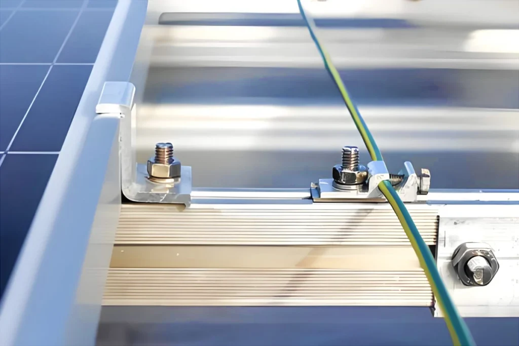
Como os painéis solares são aterrados?
Geralmente, furos de aterramento nos painéis solares são usados para conectar entre cadeias de painéis. Os painéis em ambas as extremidades da corda estão conectados à estrutura metálica, principalmente usando cabos de aterramento solar verde-amarelo.
Para aterrar as molduras do painel, hastes de aço ligadas com cobre de φ10 ou φ12 são normalmente usadas, enterrado 1.5 metros subterrâneos.
A resistência de aterramento dos painéis solares não deve exceder 4Ω. Se o requisito de resistência de aterramento não for atendido, agentes redutores de resistência são geralmente adicionados, ou as hastes de aterramento estão enterradas em áreas com menor resistividade do solo.
Saiba mais sobre Cabo de aterramento solar
Por que as estruturas dos painéis solares devem ser conectadas e aterradas?
Algumas pessoas acreditam que, uma vez que tanto os painéis solares como as suas estruturas de suporte são metálicos, apenas aterrar os suportes é suficiente.
Na realidade, a maioria das molduras de alumínio do painel solar e suportes galvanizados ou de liga de alumínio são revestidos, que não atende aos requisitos de aterramento. Adicionalmente, painéis solares podem envelhecer com o tempo, potencialmente levando a correntes de fuga excessivas ou baixa resistência de isolamento ao aterramento. Se as estruturas do painel solar não estiverem aterradas, após um período de uso, isso pode resultar em falhas do inversor, impedindo que o sistema fotovoltaico gere eletricidade adequadamente.
Ao conectar estruturas de painéis solares a suportes metálicos, é necessário remover a camada de óxido das superfícies metálicas para reduzir a impedância de aterramento, garantindo que atenda aos requisitos de aterramento.
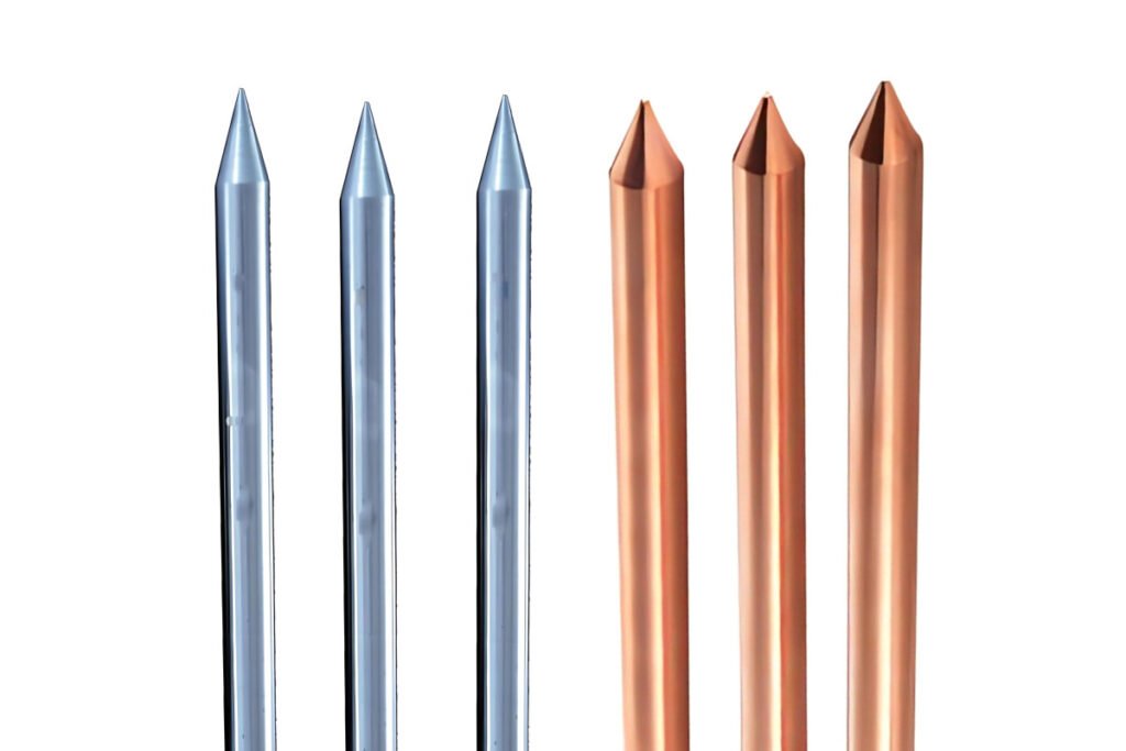
Qual material deve ser usado para haste de aterramento em sistemas fotovoltaicos?
O aço galvanizado é mais barato, Mas tem muitas articulações soldadas, resultando em menor eficiência de construção e custos de construção mais altos. Puro cobre tem excelente condutividade, mas é caro. Aço ligado a cobre, no entanto, Apenas custos 9.4% mais do que aço galvanizado e oferece uma vida de serviço muito mais longa. Portanto, As hastes de terra elétrica de aço ligadas ao cobre são tipicamente escolhidas como o principal material de aterramento em sistemas de energia solar.
Quais especificações das barras de terra são comumente usadas?
Aço ligado a cobre
Em sistemas de energia fotovoltaica, O corpo de aterramento horizontal dos materiais de aterramento de aço ligado a cobre geralmente usa φ10-a aço redondo ligado a cobre de cobre, com um comprimento de fabricação normalmente de 100 Medidores por carretel. Os eletrodos de aterramento usam φ14 ou φ17.2 hastes de aço ligadas a cobre.
Método de conexão: Soldagem térmica (Nenhuma energia externa ou acetileno necessário), usando cobre puro para materiais articulares, sem necessidade de medidas anticorrosão nos pontos de soldagem.
Aço galvanizado
Nas grades de aterramento tradicionais, Os corpos de aterramento horizontal feitos de aço galvanizado a quente são geralmente projetados com especificações de aço plano galvanizado 50x5 ou 60x6, com um comprimento de fabricação de 6 Medidores por peça. Os eletrodos de aterramento vertical usam 50x5 de aço ângulo galvanizado de 50x5 ou tubos de aço galvanizado φ50, com um comprimento de eletrodo de aterramento de 2.5 Medidores por peça.
Método de conexão: Soldagem elétrica, com os pontos de soldagem que precisam de tratamento anticorrosão, como duas demãos de tinta anti-rust e uma camada de tinta de asfalto.
Cobre nu
Para materiais de aterramento puro de cobre, O corpo de aterramento horizontal geralmente usa 25×4, 40×4, 50×5, ou 60×6 MM tiras de cobre, ou S70/S95/S120/S150/S185/S240 mm fios de cobre vazios. O corpo de aterramento vertical normalmente usa 16×2500 mm ou 20×2500 MM hastes de cobre, ou 50×3000 mm ou 55×2500 mm eletrodos de aterramento de íons eletrolíticos de cobre puro.
Método de conexão: Soldagem térmica, soldagem de derretimento de lama de fogo, ou soldagem a quente.
Saiba mais sobre Haste de aterramento para sistema fotovoltaico
Como as hastes de terra devem ser instaladas em sistemas fotovoltaicos?
Durante a construção, A instalação de uma haste moída é muito flexível e pode ser adaptada às condições específicas no local. Vários métodos podem ser usados, como dirigir diretamente as barras moídas elétricas no solo com martelos pesados ou martelos elétricos. Em condições complexas do solo, onde a haste não pode ser conduzida em, Um buraco pode ser perfurado primeiro antes de instalar a haste de solo.
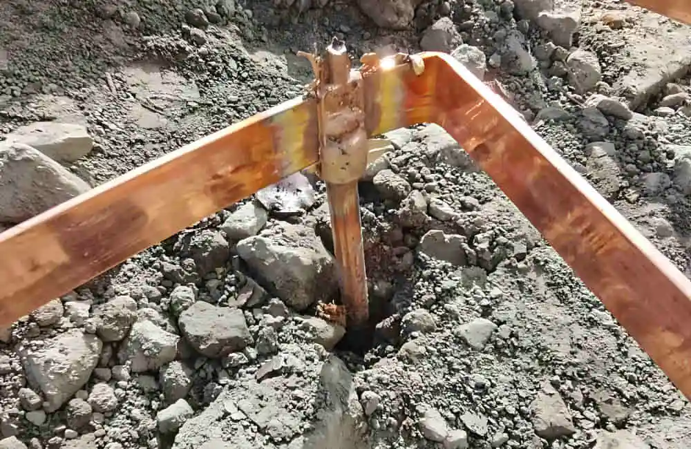
Em condições uniformes do solo, Se estiver usando um martelo pesado para instalação e dirigir uma única haste, É aconselhável instalar uma broca (Parafuso resistente ao impacto) Na extremidade pontiaguda da haste para evitar danos à camada de cobre quando a haste é acionada. Para aterramento mais profundo, Várias hastes podem ser conectadas usando conectores para obter o comprimento desejado, Garantir uma boa conexão elétrica.
Nos casos em que a perfuração profunda é difícil ou impossível, Ferramentas de perfuração podem ser usadas para penetrar nas rochas. Depois de perfurar, Existem dois métodos para instalar as hastes de terra:
- Conecte as bielas ao comprimento desejado usando conectores. Uma vez perfurado para a profundidade pretendida, Encha o orifício com um agente redutor de resistividade e adicione água até que o orifício seja preenchido.
- Conecte as bielas ao comprimento desejado usando conectores. Depois de perfurar a profundidade pretendida, Misture o agente redutor de resistividade com água e despeje no buraco para envolver totalmente a haste.
Cabos aéreos, Cabos de controle e cabos de comunicação em projetos fotovoltaicos
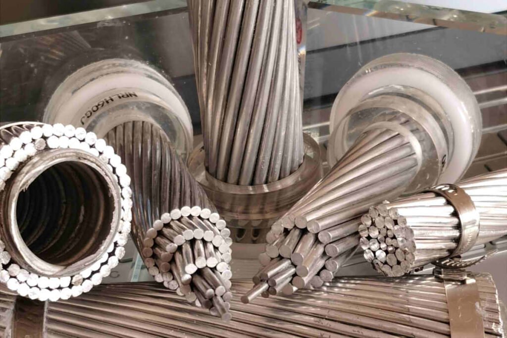
Qual cabo aéreo usar em sistemas de energia solar?
Em sistemas de geração de energia fotovoltaica conectados à rede, uma vez que a energia CC gerada é convertida em energia CA pelo inversor e integrada na rede CA, a transmissão de energia é frequentemente realizada através de linhas aéreas. Tipicamente, o processo de conexão à rede de sistemas de geração de energia fotovoltaica pode ocorrer nos seguintes cenários:
Conexão Direta
Para pequenos sistemas distribuídos de geração de energia fotovoltaica, como energia fotovoltaica em telhados residenciais, a energia CC pode ser convertida diretamente em energia CA através do inversor e depois conectada à rede de baixa tensão através de linhas de distribuição. Nesse caso, cabos subterrâneos de baixa tensão e cabos isolados aéreos, como cabos ABC, podem ser usados.
Conexão através de Transformadores Caixa ou Integração com Subestação
Centrais fotovoltaicas de média ou comercial escala podem usar subestações tipo caixa (transformadores de caixa) para converter a energia CC gerada em energia CA adequada para integração na rede através do inversor, e, em seguida, aumente a tensão através do transformador de caixa para corresponder ao nível de tensão da rede aérea, antes de conectar a linhas aéreas.
Centrais de energia fotovoltaica montadas no solo em grande escala normalmente requerem um transformador para aumentar a tensão para um nível mais alto para uma transmissão eficiente. Nesse caso, a energia está diretamente conectada a uma subestação, que então o distribui para redes aéreas de alta tensão ou ultra-alta tensão.
Nestes dois cenários, se a distância da central eléctrica ao ponto de ligação à rede for relativamente curta e a carga não for grande, O cabo AAC pode ser uma escolha econômica. Para distâncias médias ou onde é necessário um melhor desempenho físico, O cabo AAAC pode ser uma opção melhor. Para transmissão de longa distância ou onde são necessários requisitos especiais de resistência do cabo, especialmente quando as linhas aéreas precisam atravessar terrenos complexos ou resistir a condições climáticas extremas, O condutor ACSR será a escolha mais adequada.
Saiba mais sobre Cabo aéreo para sistema solar
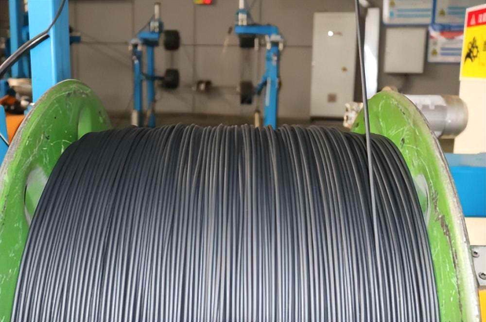
Os cabos de comunicação afetam a precisão da contagem do sistema de geração de energia solar?
Em um sistema de geração de energia solar, a função principal dos cabos de comunicação é transmitir sinais de controle e dados de monitoramento, como saída de energia, status do sistema, alarmes de falha, e outras informações. Esses cabos não participam diretamente na transmissão de energia elétrica. Portanto, os próprios cabos de comunicação não afetam diretamente a precisão da contagem em um sistema de geração de energia solar.
No entanto, se os cabos de comunicação apresentarem falhas (como atenuação de sinal, interferência, ou desconexões), isso pode fazer com que o sistema de monitoramento seja incapaz de receber ou transmitir dados com precisão, afetando assim a precisão e a oportunidade do monitoramento do sistema. Por exemplo, atrasos ou erros na transmissão de dados podem impedir que o pessoal de manutenção compreenda prontamente o status operacional real do sistema de geração de energia ou levar ao registro de dados imprecisos, impactando assim as estatísticas e análises de geração de energia.
Portanto, enquanto os cabos de comunicação não afetam a produção real de energia elétrica, eles são cruciais para a gestão e manutenção eficazes do sistema. Isto está indiretamente relacionado com a avaliação geral do desempenho e otimização da eficiência do sistema de geração de energia solar.. Garantir a qualidade e a manutenção adequada dos cabos de comunicação é essencial para manter um monitoramento confiável e uma operação eficiente do sistema de geração de energia solar.
Saiba mais sobre Cabo de comunicação e controle para sistema fotovoltaico
Requisitos legais e regulamentares para roteamento de cabos em projetos solares
Compreendendo a conformidade regulatória
Ao planejar e executar um projeto solar, é essencial cumprir vários requisitos legais e regulamentares para garantir a segurança, eficiência, e conformidade com os regulamentos locais, nacional, e padrões internacionais. Órgãos reguladores e políticas regem a instalação e operação de sistemas de energia solar, incluindo o roteamento e seleção de cabos. Compreender esses requisitos é crucial para a conclusão bem-sucedida do seu projeto solar.
Principais órgãos reguladores e padrões
Código Elétrico Nacional (NEC)
Nos Estados Unidos, o Código Elétrico Nacional (NEC) define o padrão para a instalação segura de fiação e equipamentos elétricos. Artigo 690 do NEC aborda especificamente a energia solar fotovoltaica (PV) sistemas, cobrindo aspectos como métodos de fiação, aterramento, e proteção contra sobrecorrente. A adesão às diretrizes da NEC garante que o roteamento de seus cabos atenda aos padrões de segurança e desempenho.
Comissão Eletrotécnica Internacional (CEI)
A Comissão Eletrotécnica Internacional (CEI) desenvolve padrões internacionais para todos os equipamentos elétricos, eletrônico, e tecnologias relacionadas. CEI 62548:2016 fornece diretrizes para o projeto e instalação de painéis solares fotovoltaicos, incluindo gerenciamento e roteamento de cabos. A conformidade com os padrões IEC é frequentemente exigida para projetos internacionais.
Códigos de construção locais
Os códigos de construção locais podem impor requisitos adicionais para instalações solares, incluindo roteamento de cabos. Esses códigos podem variar significativamente por região, por isso é essencial consultar as autoridades locais e garantir o cumprimento de todos os regulamentos relevantes.
Melhores práticas para roteamento de cabos
Rotulagem e documentação adequadas
Certifique-se de que todos os cabos estejam devidamente etiquetados e que a documentação abrangente seja mantida. Isso inclui diagramas de roteamento de cabos, especificações dos cabos utilizados, e registros de inspeções e aprovações. A documentação adequada facilita a conformidade regulatória e simplifica a manutenção futura.
Uso de conduítes e bandejas
O uso de conduítes e bandejas de cabos para roteamento pode proteger os cabos contra danos físicos, reduzir o risco de falhas elétricas, e aumentar a segurança geral da instalação. Certifique-se de que os conduítes e bandejas atendam aos padrões relevantes e estejam instalados corretamente.
Aterramento e ligação
O aterramento e a ligação adequados são essenciais para a segurança e o desempenho dos sistemas de energia solar. Certifique-se de que os métodos de aterramento estejam em conformidade com NEC, CEI, e padrões locais. Isso inclui o uso de condutores de aterramento apropriados, conectores, e hastes, e garantindo que todos os componentes metálicos estejam adequadamente ligados.
Inspeções e manutenção regulares
Inspeções e manutenção regulares são essenciais para garantir que o roteamento de cabos permaneça em conformidade com os requisitos regulamentares e continue a operar com segurança e eficiência. Agende inspeções periódicas para identificar e resolver quaisquer problemas, como danos físicos, vestir, ou corrosão.
Conselhos essenciais para comprar cabos
Entenda os requisitos do seu sistema
Antes de comprar cabos, é vital ter uma compreensão clara dos requisitos do seu sistema solar. Considere o tamanho do sistema, os tipos de componentes usados, e as condições ambientais. Certifique-se de que os cabos escolhidos podem suportar a carga elétrica esperada e são adequados às condições específicas do seu local de instalação.
Priorize Qualidade e Certificação
Opte sempre por cabos de alta qualidade certificados por padrões respeitáveis, como TÜV, UL, ou IEC. Cabos certificados são testados quanto à durabilidade, segurança, e desempenho, garantindo que atendam aos padrões da indústria. O uso de cabos certificados ajuda a evitar possíveis problemas, como perda de energia, superaquecimento, ou riscos de incêndio.
Escolha os tipos de cabos corretos
Selecione cabos projetados especificamente para aplicações solares. Para aplicações CC, Cabos fotovoltaicos como H1Z2Z2-K e PV1-F são ideais devido à sua resistência à radiação UV, variações de temperatura, e estresse mecânico. Para aplicações de CA, certifique-se de usar cabos apropriados de baixa e média tensão.
Considere os fatores ambientais
Leve em consideração as condições ambientais no local de instalação. Cabos expostos a condições climáticas adversas, Radiação UV, ou temperaturas extremas devem ser escolhidas pela sua resiliência a estas condições. O isolamento adequado e as medidas de proteção prolongarão a vida útil dos cabos e manterão a eficiência do sistema.
Garanta instalação e manutenção adequadas
A instalação adequada é tão crucial quanto selecionar os cabos corretos. Siga as práticas recomendadas para roteamento de cabos, aterramento, e proteção para evitar danos físicos e falhas elétricas. Manutenção e inspeções regulares são essenciais para garantir a segurança e o desempenho contínuos do seu sistema de energia solar.
Plano para conformidade regulatória
Esteja ciente do local, nacional, e regulamentos internacionais que se aplicam ao seu projeto solar. Certifique-se de que a seleção e instalação do cabo estejam em conformidade com esses padrões para evitar problemas legais e garantir a segurança e a confiabilidade do seu sistema.
Considerações Finais
Investir tempo e recursos na seleção dos cabos certos para o seu projeto solar compensa no longo prazo. Cabos de qualidade garantem transmissão de energia eficiente, reduzir custos de manutenção, e melhorar a segurança e confiabilidade geral do seu sistema. Seguindo as diretrizes e práticas recomendadas descritas neste guia, você pode tomar decisões informadas que contribuem para o sucesso de sua instalação solar.
Lembrar, um sistema de energia solar bem projetado não envolve apenas painéis e inversores; os cabos que conectam esses componentes são igualmente importantes. Certifique-se de priorizar a qualidade, conformidade, e instalação adequada para aproveitar todo o potencial do seu sistema de energia solar.