
Выбор воздушного кабеля для фотоэлектрической установки является важнейшим аспектом проектирования и эффективной эксплуатации таких объектов.. Правильный размер воздушного проводника напрямую влияет на безопасность., потери энергии, эксплуатационные расходы, и долгосрочная прибыльность.
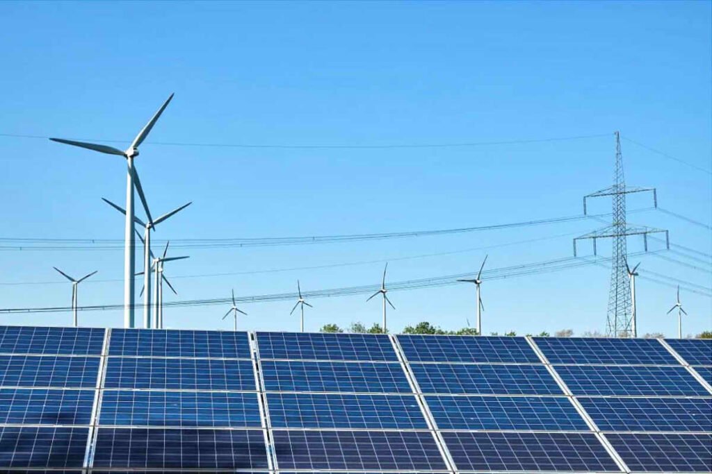
Фотоэлектрические установки делятся на централизованные и распределенные фотоэлектрические установки в зависимости от их мощности и способа потребления.. Централизованные электростанции имеют более высокую мощность и обычно подключаются к сети с использованием напряжения 35 кВ/110 кВ или выше., доступ к ближайшей подстанции 35 кВ/110 кВ. Подстанции 35 кВ/110 кВ обычно располагаются в городских центрах нагрузки., на определенном расстоянии от фотоэлектрической установки. Для снижения затрат и повышения эффективности, голый антенный кабель обычно используется для подключения электростанции к подстанции.
При проектировании фотоэлектрической установки и выборе кабелей, использование голого проводника меньшего сечения снижает расход цветных металлов, тем самым снижая инвестиционные затраты. С другой стороны, если используется проводник большего сечения, сопротивление на единицу длины уменьшается, что снижает потери активной энергии, перепады напряжения, и потери электрической энергии, как следствие, снижение эксплуатационных расходов. Для снижения потерь в сети и повышения экономической эффективности фотоэлектрической станции., максимизация доходов от производства энергии, важно правильно подобрать сечение проводника.
Три необходимых условия выбора сечения проводника
Выбор сечения ВЛ должен обеспечивать безопасность людей., надежное электроснабжение, передовые технологии, и разумная экономия. Технически, выбор должен отвечать следующим трем необходимым требованиям:
Состояние механического сопротивления
При длительной эксплуатации, на проводник будут действовать различные внешние силы, например, натяжение линии, собственный вес проводника, ветер, и накопленный вес льда. Обеспечить безопасность и надежность работы кондуктора., необходимо, чтобы он имел достаточную механическую устойчивость. В нормативных актах указано, что для обеспечения механической стойкости линий электропередачи, поперечное сечение проводника не должно быть меньше значений, указанных в следующей таблице.:
| Тип дирижера | Через жилые районы | Через нежилые помещения |
|---|---|---|
| Плетеный кабель из алюминия и алюминиевых сплавов | 35 | 25 |
| Плетеный кабель со стальным сердечником | 25 | 16 |
| Медный кабель | 16 | 16 |
Условия нагрева
Когда ток течет по проводнику, он нагревается из-за сопротивления. Чтобы предотвратить преждевременное выгорание или старение проводника из-за перегрева., и обеспечить его безопасную и надежную долгосрочную эксплуатацию., он также должен соответствовать условиям повышения температуры. То есть, Максимальный непрерывный ток нагрузки, протекающий через проводник, должен быть меньше, чем допустимый долговременный безопасный непрерывный ток.. Стандарт устанавливает долговременный безопасный непрерывный ток при температуре окружающей среды 25°C., как показано в следующей таблице:
| Поперечное сечение / мм² | 35 | 50 | 70 | 95 | 120 | 150 | 185 | 240 | 300 | 400 | 500 |
|---|---|---|---|---|---|---|---|---|---|---|---|
| ЖЖ | 170 | 215 | 265 | 325 | 375 | 440 | 500 | 610 | 680 | 830 | 980 |
| LGJ | 170 | 220 | 275 | 335 | 380 | 445 | 515 | 610 | 700 | 800 | – |
| LJGQ | – | – | – | – | – | – | 510 | 610 | 710 | 845 | 966 |
Состояние эффекта короны
В воздушных линиях высокого напряжения, напряженность окружающего электрического поля высока. Это может привести к возникновению частичных или полных разрядов., увеличение потерь энергии, создание помех связи, и ускорение окисления оборудования. Чтобы избежать эффекта короны, напряженность электрического поля в окружающем воздухе необходимо уменьшить за счет увеличения сечения проводника. Когда уровень напряжения ниже 60 кВ, а полный эффект короны не происходит из-за низкого рабочего напряжения и малой напряженности электрического поля.. Однако, когда уровень напряжения равен или превышает 110 кВ, минимально необходимое сечение проводника во избежание эффекта коронного разряда следующее::
| Номинальное напряжение / кВ | 110 | 220 | 330 |
|---|---|---|---|
| Минимальное сечение проводника | LGJ-70 | LGJ-300 | LGJ-2×240 |
Метод выбора сечения проводника 1: Метод экономической плотности тока
При учете экономии при выборе сечения проводника, необходимо в первую очередь учитывать инвестиции в строительство линии и ежегодные эксплуатационные расходы, которые в основном основаны на потерях энергии. Обеспечить экономическую целесообразность выбора проводников., оно должно основываться на плотности экономического тока. После всестороннего рассмотрения принципов общей выгоды (инвестиции, эксплуатационные расходы, коэффициент возврата инвестиций, норма амортизации), наиболее экономичный ток, соответствующий единице сечения проводника, называется экономической плотностью тока.. Это связано с материалом проводника., коэффициент использования линии, и сумма инвестиций. На практике, определяется в зависимости от материала проводника, часы максимальной загрузки, и номинальное напряжение, как показано в таблице. Сечение, выбранное в соответствии с экономической плотностью тока, называется экономическим сечением., определяется как:
Sj = Iмакс / Дж
- Сджей: Экономический срез
- Дж: Экономическая плотность тока
- Imax: Максимальный рабочий ток проводника в нормальных условиях
| Т(Макс)/час | 2000 | 3000 | 4000 | 5000 | 6000 | 7000 |
|---|---|---|---|---|---|---|
| ЖЖ Дирижер 10 кВ или меньше | 1.44 | 1.18 | 1.00 | 0.86 | 0.76 | 0.66 |
| LGJ Дирижер 10 кВ или меньше | 1.70 | 1.38 | 1.18 | 1.00 | 0.88 | 0.78 |
| LCJ Дирижер 35 кВ или более | 1.86 | 1.50 | 1.26 | 1.08 | 0.94 | 0.84 |
Пример выбора воздушного кабеля для фотоэлектрической установки
Реальный сценарий
Для решение для фотоэлектрического кабеля, в воздушной линии 35кВ, используется кабель в алюминиевой оплетке со стальным сердечником и двойной цепью., с длиной 15 км и максимальной нагрузкой 16 МВ в конце. Средний коэффициент мощности 0.9, и максимально допустимое падение напряжения 5% в нормальных условиях допускается. Необходимо подобрать сечение проводника..
План отбора
Сечение проводника будет выбрано исходя из экономической плотности тока., а затем будет проверено по трем необходимым условиям и допустимому падению напряжения.
Максимальный рабочий ток:
Iмакс = (П / 2) / (1.732 × UN × cosθ) = (16000 / 2) / (1.732 × 35 × 0.9) = 146.63 А
При максимальном рабочем токе (Imax) из 146.63 A и Tmax 2000 часы, в таблице указано, что экономическая плотность тока (Дж) является 1.65 А/мм². Поэтому, экономический срез:
Sj = Iмакс / Дж = 146.63 / 1.65 = 88.87 мм²
Выбирается ближайшее сечение: Водитель LGJ-95, с параметрами ro + jxo = 0.332 + j0,4 Ом/км и длительный безопасный непрерывный ток 335 А.
Проверка
- Механическое сопротивление:
С = 95 мм² > И = 25 мм²
Соответствует требованиям. - Условия нагрева:
Поскольку двухцепная линия может работать в одной цепи, ток в линии увеличивается, генерировать больше тепла. Это наиболее критический сценарий эксплуатации.. При проверке температуры, этот режим работы следует учитывать:
Iмакс = 2 × 146.63 А = 293.26 А < я = 335 А
Соответствует требованиям. - Состояние эффекта короны:
Поскольку линия 35 кВ, нет необходимости проверять условие эффекта коронного разряда. - Падение напряжения:
ΔU = (П × Р + К × Х) × Л / У = 1.80 кВ
U% = 1.80 / 35 = 5.15% > 5%
Не соответствует требованиям, поэтому сечение проводника надо увеличить. Выбран проводник LGJ-120., с параметрами ro + jxo = 0.236 + j0,421 Ом/км и длительный безопасный непрерывный ток 380 А.
Новая проверка:
- Механическое сопротивление:
С = 120 мм² > И = 25 мм²
Соответствует требованиям. - Условия нагрева:
Iмакс = 2 × 146.63 А = 293.26 А < я = 380 А
Из таблицы видно, что проводник LGJ-120 имеет максимальный безопасный ток 380 А в режиме отказа, больше максимального тока в проводнике, так что он соответствует требованиям. - Состояние эффекта короны:
Поскольку линия 35 кВ, нет необходимости проверять условие эффекта коронного разряда. - Падение напряжения:
ΔU = (П × Р + К × Х) × Л / У = 1.60 кВ
U% = 1.60 / 35 = 4.57% < 5%
Соответствует требованиям.
Поэтому, выбранный воздушный проводник LGJ-120 подходит.
Заключение
Правильный подбор средства кабели на фотоэлектрической установке важно для обеспечения как безопасности, так и эффективности. Учитывая три основных критерия — механическое сопротивление, обогрев, и условия коронного разряда — гарантировано, что проводник выдержит физические и термические нагрузки., минимизация потерь энергии и оптимизация эксплуатационных расходов.
Использование метода экономической плотности тока позволяет сбалансировать первоначальные инвестиции и долгосрочные затраты.. Регулируя сечение проводника в соответствии с техническими требованиями и избегая перепадов напряжения., обеспечивается эффективная и экономичная работа установки, максимизация его производительности и долговечности.