
Dünya yenilenebilir enerjiye yönelirken, Güneş enerjisi en popüler ve sürdürülebilir elektrik kaynaklarından biri olarak ortaya çıktı. Güneş enerjisi projeleri, ister konut ister ticari, dikkatli planlama ve değerlendirme gerektirir, özellikle doğru bileşenlerin seçilmesi söz konusu olduğunda. Bu bileşenler arasında, kablolar verimliliğin sağlanmasında kritik bir rol oynamaktadır, emniyet, Güneş enerjisi sisteminin ömrü ve ömrü.
İçindekiler
- Güneş Sistemi Enerji Üretim Süreci
- Güneş Enerjisi Sistemleri İçin Ne Tür Kablolara İhtiyaç Vardır?
- Fotovoltaik Güç Santralinde Kablolar Toplam İnşaat Maliyetinin Yüzde Kaçını Temsil Ediyor??
- Solar DC Kablolar Hakkında
- Neden Fotovoltaik Sistemler İçin Özel Kablolar Kullanılmalıdır??
- Solar Kablolar için TÜV Sertifikası Nedir??
- H1Z2Z2-K PV Kabloları Hangi Özelliklerde Seçilmelidir??
- H1Z2Z2-K Fotovoltaik Kabloların DC ve AC Uygulamaları Arasındaki Farklar Nelerdir??
- H1Z2Z2-K ve PV1-F Fotovoltaik Kablolar Arasındaki Farklar Nelerdir??
- PV1-F Kablo Spesifikasyonu Nasıl Seçilir?
- Güneş Kabloları Neden Kırmızı ve Siyaha Ayrılıyor??
- Solar Kablo Konnektörlerini Kendiniz Yapabilir misiniz??
- Yaygın Olarak Kullanılan Güneş Konnektörleri Nelerdir??
- Solar AC Kabloları Hakkında
- Topraklama Sistemi Kabloları Hakkında
- Güneş Enerjisi Üretim Sistemleri Neden Topraklanmalıdır??
- Güneş Enerjisi Sistemlerinde Hangi Topraklama Gereklidir?
- Güneş Panelleri Nasıl Topraklanır??
- Güneş Panellerinin Çerçeveleri Neden Bağlanmalı ve Topraklanmalıdır??
- Fotovoltaik Sistemlerde Topraklama Çubuğu Hangi Malzeme Kullanılmalıdır??
- Toprak Çubuklarının Hangi Özellikleri Yaygın Olarak Kullanılır??
- Fotovoltaik Sistemlerde Topraklama Çubukları Nasıl Takılmalıdır??
- Havai Kablolar, PV Projelerinde Kontrol Kabloları ve Haberleşme Kabloları
- Güneş Enerjisi Projelerinde Kablo Yönlendirmesine İlişkin Yasal ve Düzenleyici Gereksinimler
- Kablo Yönlendirme için En İyi Uygulamalar
- Kablo Satın Alma Konusunda Temel Tavsiyeler
- Son Düşünceler
Güneş enerjisi projeniz için uygun kabloları seçmek göz korkutucu bir iş olabilir, Mevcut seçeneklerin çeşitliliği ve fotovoltaiğin özel gereksinimleri göz önüne alındığında (PV) sistemler. Bu kılavuz, güneş enerjisi projeniz için kablo satın alma konusunda bilmeniz gereken her şeye kapsamlı bir genel bakış sunmayı amaçlamaktadır.. Güneş enerjisi üretim sürecini anlamaktan farklı uygulamalar için doğru kablo türlerini seçmeye kadar, bilinçli kararlar vermenize yardımcı olacak tüm önemli hususları ele alacağız.
Bu kılavuzun sonunda, Güneş enerjisi projeniz için kablo satın alırken dikkate almanız gereken kritik faktörleri net bir şekilde anlayacaksınız, Sisteminizin gelecek yıllar boyunca verimli ve güvenli bir şekilde çalışmasını sağlamak.
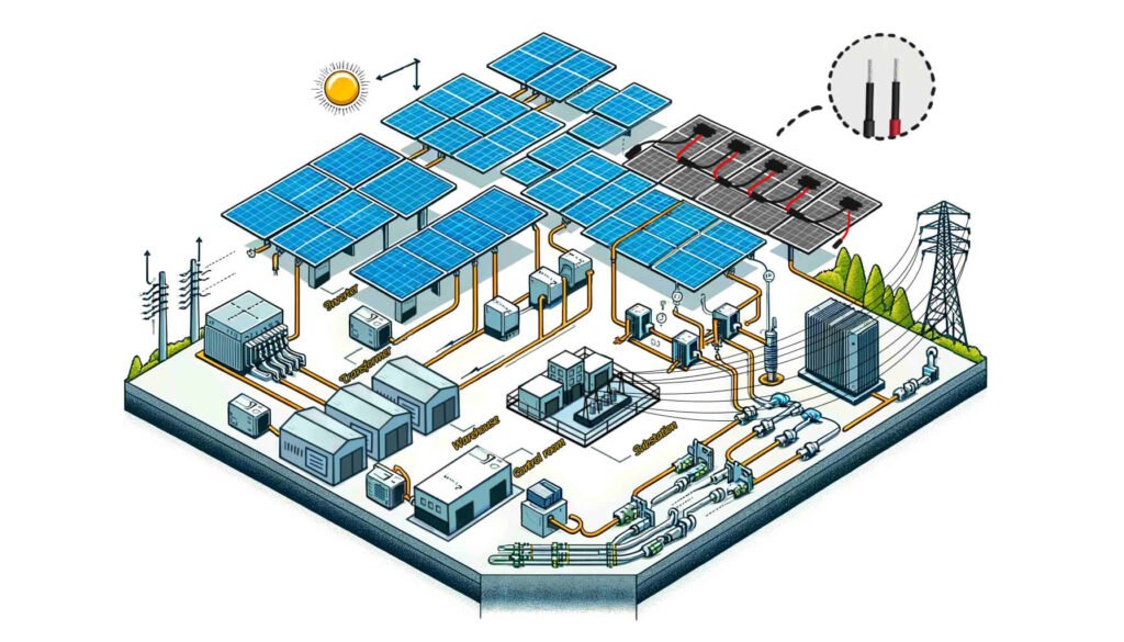
Güneş Sistemi Enerji Üretim Süreci
Güneş enerjisi sistemi enerji üretimi süreçlerini anlamak, PV projeniz için doğru kabloları ve bileşenleri seçmek açısından çok önemlidir.. Doğru kablo seçimi, elektriğin sistem genelinde verimli ve güvenli iletimini sağlar, ister şebekeye bağlı ister şebekeden bağımsız bir kurulum olsun.
1. Güneş Panelleri Güneş Işığını Yakalar
Güneş panelleri, çok sayıda güneş pilinden oluşur, fotonlar olduğunda güneş ışığını yakalayın (hafif parçacıklar) yüzeye vurmak. Bu fotonlar enerjilerini güneş pillerindeki elektronlara aktarırlar., elektrik akımı oluşturmak.
2. Elektrik Üretimi
Fotonlardan gelen enerji elektronlara enerji verir, akmalarına ve doğru akım üretmelerine neden olur (DC). Güneş panelleri genellikle önemli miktarda elektrik üretmek için büyük diziler halinde düzenlenir., evlere elektrik sağlamak için yeterli, işletmeler, veya tüm topluluklar.
3. İnvertör Dönüşümü
Güneş panelleri tarafından üretilen DC elektrik çoğu ev aleti ve ticari ekipman tarafından doğrudan kullanılamaz., alternatif akımla çalışan (klima). Bu açığı kapatmak için, DC elektriğini AC elektriğe dönüştürmek için bir invertör kullanılır, standart elektrik sistemleriyle uyumlu hale getirilmesi.
4. İletim ve Dağıtım
AC'ye dönüştürüldükten sonra, elektrik bir transformatöre gönderilir. Transformatör elektriğin voltajını artırır, Bu, elektrik hatları aracılığıyla uzun mesafelerde verimli bir şekilde iletilmesine olanak tanır. Yüksek voltajlı AC gücü daha sonra şebeke aracılığıyla çeşitli tüketicilere dağıtılır., evler ve işyerleri dahil.
Şebekeye Bağlı Sistemler
Şebeke bağlantılı sistemlerde, süreç aşağıdaki gibidir:
- PV Paneller DC Güç Üretir: Güneş panelleri güneş ışığını yakalar ve DC gücü üretir.
- İnvertör AC Gücüne Dönüştürür: DC gücü, invertör tarafından AC gücüne dönüştürülür.
- Trafo Gerilimi Artırır: Gerekirse, bir transformatör verimli iletim için voltajı artırır.
- Şebekeye İletim: AC gücü havai hatlar aracılığıyla şebekeye iletilir.
Bu sistemde, elektrik enerjisi, invertör aşamasında yalnızca bir kez DC ve AC arasında dönüştürülür. Dönüşümden sonra, elektrik AC formunda iletilir ve kullanılır.
Şebekeden Bağımsız Sistemler
Şebekeden bağımsız sistemlerde, süreç biraz farklı:
- PV Paneller DC Güç Üretir: Güneş panelleri güneş ışığını yakalar ve DC gücü üretir.
- İnvertör AC Gücüne Dönüştürür: DC gücü, invertör tarafından AC gücüne dönüştürülür.
- Trafo Gerilimi Artırır: Gerekirse, bir transformatör voltajı arttırır.
- Doğrudan Kullanım veya Depolama: AC gücü, anında kullanım için doğrudan kullanıcının şebekesine bağlanabilir veya daha sonra kullanılmak üzere pillerde saklanabilir..
Şebekeden bağımsız sistemler, sürekli güç kaynağı sağlamak için akü depolamaya dayanır, güneş ışığı mevcut olmasa bile, örneğin gece veya bulutlu günlerde.
Güneş enerjisi üretim sürecini öğrendikten sonra, tüm sistem için hangi kabloların gerekli olduğunu belirleyebiliriz.
Güneş Enerjisi Sistemleri İçin Ne Tür Kablolara İhtiyaç Vardır?
Sürdürülebilir enerji çözümlerinin önemli bir bileşeni olarak, Güneş enerjisi üretim sistemlerinin güvenli ve verimli çalışması, çeşitli özel kabloların uygun konfigürasyonuna ve kullanımına bağlıdır.. Güneş enerjisi üretim sisteminde gerekli olan kablo türleri aşağıdakileri içerir::
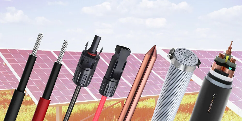
Güneş DC Kablosu
Bu kablolar özellikle fotovoltaik modülleri bağlamak için tasarlanmıştır. (güneş panelleri) ve modüller arasında DC birleştirici kutusuna güç aktarımı için. Dış ortamlara doğrudan maruz kaldıkları göz önüne alındığında, aşağıdaki özelliklere sahip olmaları gerekir:
- UV Dayanımı: Uzun süre güneşe maruz kalma nedeniyle performans bozulmasını önlemek için.
- Hava Şartlarına Direnç: Çeşitli hava koşullarına dayanmak için, aşırı sıcaklıklar dahil, nem, ve rüzgarın savurduğu kum.
- Tuz Püskürtme Korozyon Direnci: Tuz hasarını önlemek için kıyı bölgelerine uygundur.
- Alev Geciktirme: Yangın risklerini azaltmak ve sistem güvenliğini artırmak için.
- Mekanik Dayanım: Kolayca zarar görmeden kurulum ve çevre baskılarına dayanmak.
AC Kablosu
AC kabloları, dönüştürülen AC gücünü AC dağıtım panosuna veya doğrudan şebekeye iletmek için invertör çıkış ucunda kullanılır. Güvenli ve verimli güç iletimi sağlamak için bu kabloların şebeke bağlantı standartlarını karşılaması ve iyi yalıtım özelliklerine ve ısı direncine sahip olması gerekir..
Veri İletişim Kablosu
Güneş enerjisi üretim sisteminde, veri iletişim kabloları bilgi köprüsü görevi görür. Yalnızca fotovoltaik dizi tarafından üretilen elektriksel verileri iletmekle kalmaz, aynı zamanda invertörlerin ve diğer izleme ekipmanlarının gerçek zamanlı durum bilgilerini kablolu veya kablosuz ağlar aracılığıyla merkezi izleme sistemine iletirler. (fiber optik dahil) sistem optimizasyonu ve arıza teşhisi için.
Kontrol kablosu
Kontrol kabloları denetleyicileri bağlamak için kullanılır, invertörler, ve sistemdeki diğer yardımcı ekipmanlar, otomatik kontrolün ve etkili izlemenin sağlanması. Bu kabloların, kontrol komutlarının doğru şekilde yürütülmesini sağlamak için iyi sinyal iletim kararlılığına ve parazit önleme özelliklerine sahip olması gerekir..
Topraklama Kablosu
Topraklama kabloları tüm güneş enerjisi üretim sisteminin güvenlik korumasında kritik bir rol oynar. Yıldırım akımlarını veya sistem arıza akımlarını hızla boşaltmak için düşük dirençli bir yol sağlarlar, elektrik çarpmasını ve ekipman hasarını önleme, Böylece personel ve ekipmanın güvenliği sağlanır.
Havai kablo
Belirli kurulum senaryolarında, uzun mesafe iletim veya arazi kısıtlamaları gibi, Güneş enerjisi üretim sisteminin şebeke bağlantısı için havai kablolar kullanılır. Bu kabloların, iyi iletkenliği ve mekanik mukavemeti korurken, harici fiziksel hasarlara ve iklim faktörlerine dayanacak şekilde özel olarak tasarlanması gerekir..
Bu solar kabloları seçerken, Güneş enerjisi üretim sisteminin uzun vadeli istikrarlı çalışmasını ve uyumluluğunu sağlamak için yalnızca özelliklerini ve geçerli ortamları dikkate almak değil, aynı zamanda tüm kabloların ve aksesuarların yerel elektrik güvenliği standartlarına ve endüstri düzenlemelerine uygun olmasını sağlamak da önemlidir..
Fotovoltaik Güç Santralinde Kablolar Toplam İnşaat Maliyetinin Yüzde Kaçını Temsil Ediyor??
Fotovoltaikte kabloların maliyeti (PV) elektrik santrali tipik olarak etrafı temsil eder 10% toplam inşaat maliyetinin. Bu yüzde, projenin ölçeği gibi çeşitli faktörlere bağlı olarak değişebilir., ekipman seçimi, bölgesel farklılıklar, ve piyasa dalgalanmaları. Bazı tahminlere göre:
- Fotovoltaik modüller (güneş panelleri) yaklaşık olarak hesaplayın 50% toplam ekipman maliyetinin.
- İnvertörler ve diğer elektrikli ekipmanlar yaklaşık olarak 10%.
- Kablolar ve montaj yapılarının her biri yaklaşık olarak 10%.
Öyleyse, kablo maliyetleri genellikle yaklaşık olarak oluşur 10% toplam inşaat maliyetinin. Fakat, bu kaba bir tahmin, ve gerçek oran, projenin spesifik bütçesine ve malzeme fiyatlarına bağlı olarak değişiklik gösterebilir.. bunlara ek olarak, Teknolojideki ilerlemeler ve pazardaki değişikliklerle birlikte, bu yüzde ayarlamalara tabi olabilir.
Solar DC Kablolar Hakkında
Neden Fotovoltaik Sistemler İçin Özel Kablolar Kullanılmalıdır??
Fotovoltaik kablolar, fotovoltaik enerji üretim projeleri için özel olarak tasarlanmıştır., Sıradan kabloların sahip olmadığı yalıtım ve kılıf özelliklerine sahip.
PV sisteminde sıradan kablolar kullanılıyorsa, zorlu dış ortamlarda arızalanmaya eğilimlidirler, tüm güneş enerjisi sisteminin ömrünü büyük ölçüde azaltır. bunlara ek olarak, aşırı akıma yol açabilir, şiddetli voltaj düşüşü, sık üretim hataları, fotovoltaik santrallerde düşük üretim verimliliği, hatta potansiyel olarak tesiste yangına neden olabilir.
Öyleyse, fotovoltaik enerji santrallerinin uzun süreli istikrarlı çalışmasını sağlamak için 25 yıllar, fotovoltaik sistemler için özel olarak tasarlanmış kabloların seçilmesi önemlidir, H1Z2Z2-K veya PV1-F gibi.
Solar Kablolar için TÜV Sertifikası Nedir??
TÜV Solar Kablo Sertifikasyonu, test edilmiş kablolara verilen bir dizi sertifikayı ifade eder., TÜV Rheinland Grubunun bağımsız bir üçüncü tarafı tarafından denetlenmiş ve sertifikalandırılmıştır, merkezi Almanya'da, belirli standartlara uygun olarak.
Özel bir kablo türü olarak, Fotovoltaik kabloların güvenliği ve performansı, güneş enerjisi üretim sistemleri için çok önemlidir., dolayısıyla kalitelerini ve güvenilirliklerini sağlamak için sıkı testlerden ve sertifikalardan geçerler.
PV kabloları için TÜV sertifikasyonu hakkında, gelişimi 2PfG'den itibaren ilerledi 1169/08.2007 EN standardı 50618:2014 standart. En yeni standart IEC FDIS'tir 62930, ancak güneş enerjisi kablosu sertifikalarının çoğu hala geçerli EN'ye uygundur 50618 standart.
H1Z2Z2-K PV Kabloları Hangi Özelliklerde Seçilmelidir??
Tipik fotovoltaik sistemlerde, en yaygın seçenekler H1Z2Z2-K 1'dir×4 ve H1Z2Z2-K 1×6 kablolar. Genel olarak, daha büyük kablo kesitleri daha büyük yük taşıma kapasitelerini gösterir.
Çalışma voltajı gibi hususlar, mevcut kapasite, ve ortam sıcaklığı aralığı da dikkate alınmalıdır.. Gerilim ve akım gereksinimlerini belirledikten sonra, uygun spesifikasyonu seçmek için H1Z2Z2-K kablolarının parametre tablosuna bakın.
Kablo özelliklerini seçerken belirsizlikle karşılaşırsanız, ZMS teknik ekibimiz özel çözümler sunmaya hazırdır.
Hakkında daha fazla bilgi edinin H1Z2Z2-K güneş enerjisi kablosu
H1Z2Z2-K Fotovoltaik Kabloların DC ve AC Uygulamaları Arasındaki Farklar Nelerdir??
H1Z2Z2-K kablolar her iki DC devre için de kullanılabilir (1.5kV) ve AC devreleri (1.0/1.0kV). Fotovoltaik enerji üretim sistemlerinde, spesifik uygulama farklılıkları aşağıdaki gibidir:
DC Uygulamaları için:
- Fotovoltaik modüller arasında seri bağlantı
- Dizeler arasındaki paralel bağlantı
- Dizilerden DC dağıtım kutularına paralel bağlantı
- DC dağıtım kutularından invertörlere bağlantı
AC Uygulamaları için:
- İnvertörlerden yükseltici transformatörlere bağlantı
- Yükseltici transformatörlerden dağıtım cihazlarına bağlantı
- Dağıtım cihazlarından şebekeye veya kullanıcılara bağlantı
H1Z2Z2-K ve PV1-F Fotovoltaik Kablolar Arasındaki Farklar Nelerdir??
PV1-F kablosu, TÜV 2Pfg1169 standardına uygun eski versiyon bir güneş enerjisi kablosudur, ve standart sertifikasyonu güncellenmeyi durdurdu. Tersine, H1Z2Z2-K fotovoltaik kablo en son TÜV EN50618 ile uyumludur:2014 sertifikasyon.
Gerilim değerleri PV1-F ve H1Z2Z2-K kabloları arasında farklılık gösterir. PV1-F'nin voltaj değeri DC'dir: 1.0kV ve AC: Uo/U: 0.6/1.0kV, H1Z2Z2-K'nin voltaj değeri DC iken: 1.5kV ve AC: Uo/U: 1.0/1.0kV. H1Z2Z2-K daha yüksek iletim verimliliği ve kararlılığı sağlayabilir.
Yapı açısından, PV1-F kablosunun tek bir yalıtım katmanı vardır, H1Z2Z2-K kablosu ise çift katmanlı bir yalıtım yapısını benimser. Bu, H1Z2Z2-K kablosunu dayanıklılık ve koruma açısından üstün kılar, özellikle mekanik hasarlara ve çevresel faktörlere karşı.
Özetle, H1Z2Z2-K güneş enerjisi kablosunun tasarımı daha gelişmiştir, daha yüksek elektriksel ve mekanik performans sunar, daha zorlu uygulama ortamları için uygundur. Diğer taraftan, PV1-F güneş enerjisi kablosu öncelikle maliyet etkinliği açısından avantajlıdır, çoğu geleneksel fotovoltaik sistem için uygundur.
Maliyet etkinliği hususları için, PV1-F kablosu, fotovoltaik modüller arasındaki seri bağlantılar ve dizilerden DC dağıtım kutularına paralel bağlantılar için kullanılabilir. Bu sırada, H1Z2Z2-K kablosu dağıtım kutuları ve invertörler arasındaki bağlantılarda kullanılabilir, ve büyük invertörlerdeki doğru akım bağlantıları için.
PV1-F Kablo Spesifikasyonu Nasıl Seçilir?
Şu anda, en yaygın kullanılan fotovoltaik DC kablosu PV1-F 1'dir×4 kablo. Fakat, fotovoltaik modül akımlarının ve tek invertör gücünün artmasıyla, PV1-F 1'in uygulanması×6 DC kablolar da artıyor.
İlgili spesifikasyonlara göre, genellikle fotovoltaik DC güç hatlarının kaybının aşılmaması tavsiye edilir. 2%. DC devrelerinde, PV1-F 1x4mm² kablonun hat direnci 4,6mΩ/m'dir, ve PV1-F 1x6mm² kablonun hat direnci 3,1mΩ/m'dir. DC modüller için 600V çalışma voltajı varsayıldığında, A 2% voltaj düşüşü kaybı 12V. 13A modül akımı varsayarsak, 4mm² DC kablo kullanıldığında, en uzak modül ucundan invertöre kadar tavsiye edilen maksimum mesafe aşılmamalıdır 120 metre (tek dize, pozitif ve negatif kutuplar hariç). Bu mesafeyi aşarsa, 6mm² DC kablo seçilmesi tavsiye edilir, ancak en uzak modülün ucundan invertöre kadar tavsiye edilen maksimum mesafe şu değeri aşmamalıdır: 170 metre.
Sistem maliyetlerini azaltmak için, fotovoltaik enerji santralleri artık modülleri ve invertörleri nadiren yapılandırıyor 1:1 oran. Yerine, güneş ışığı koşulları ve proje gereksinimleri gibi faktörlere göre belirli miktarda fazla kapasite tasarlıyorlar. Örneğin, 110KW'lık bir modül için, 100KW'lık bir invertör seçildi, ve invertörün AC tarafındaki 1,1 kat fazla kapasiteye göre hesaplanır. Maksimum AC çıkış akımı yaklaşık 158A'dır. AC kabloları invertörün maksimum çıkış akımına göre seçilir. Çünkü modüllerin ne kadar aşırı yapılandırıldığına bakılmaksızın, İnverterin AC giriş akımı asla invertörün maksimum çıkış akımını aşmayacaktır..
Hakkında daha fazla bilgi edinin PV1-F güneş enerjisi kablosu
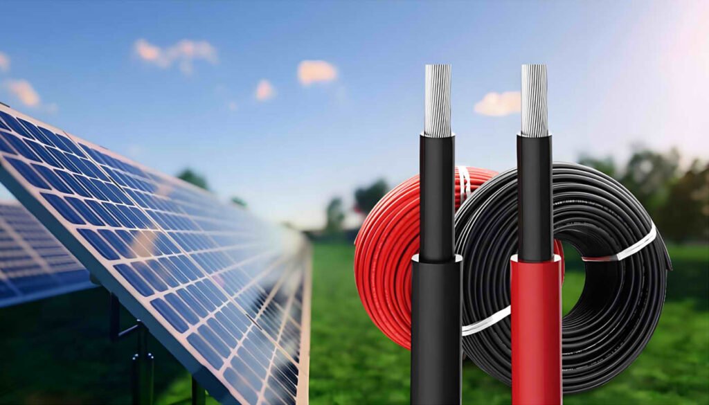
Güneş Kabloları Neden Kırmızı ve Siyaha Ayrılıyor??
Fotovoltaik endüstrisinde, kırmızı ve siyah kabloların kullanılması yaygın olarak kabul edilen bir tanımlama yöntemi haline geldi. Temel amaçları pozitif ve negatif kutupları ayırt etmektir.. DC devrelerinde, tipik olarak, kırmızı güneş kabloları akımın pozitif kutbunu gösterir, siyah güneş kabloları negatif kutbu gösterirken. Bu renk farklılaşması, güneş enerjisi sistemlerinin kurulumu ve bakımı sırasında fotovoltaik bağlantıların polaritesinin hızlı bir şekilde belirlenmesine yardımcı olur, böylece kablolama hatalarını önler.
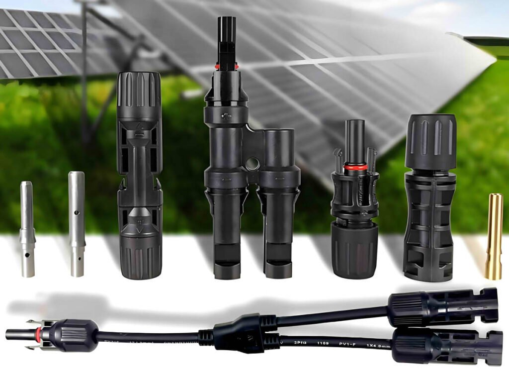
Solar Kablo Konnektörlerini Kendiniz Yapabilir misiniz??
Güneş enerjisi kablosu konnektörleri yapma süreci, erkek ve dişi damarlarda ve kafalarda hasar olup olmadığının kontrol edilmesini içerir, ve tel sıyırıcıların kullanılması, sıkma araçları, ve açık uçlu anahtarlar. Profesyonel olmayanlar bile belirli adımları izleyerek bu konnektörleri yapabilirler.
Konektörleri kendiniz yapmaya kıyasla, Güneş paneli uzatma kablolarının doğrudan özelleştirilmesi biraz daha pahalı olabilir, ancak zamandan ve işçilikten tasarruf sağlayabilir ve kurulumu daha kolay hale getirebilir.
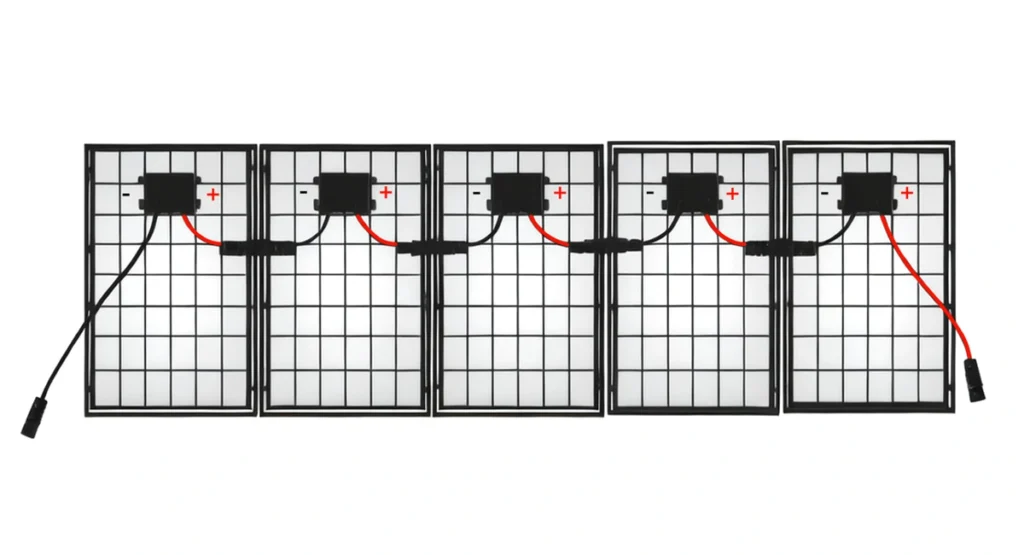
Yaygın Olarak Kullanılan Güneş Konnektörleri Nelerdir??
Solar fotovoltaik sistemlerde en sık kullanılan konnektör tipi MC4 konnektördür.. Yaygın kullanımı ve pazardaki tanınırlığı nedeniyle fotovoltaik konnektörlerde standartlardan biri haline gelmiştir.. MC4 konnektörlü uzatma kabloları, yüksek gerilim ve akıma dayanabilir ve güneş panellerini bağlamak için uygundur, invertörler, ve diğer sistem bileşenleri.
ZMS'nin MC4 uyumlu konnektörleri, teknik özelliklerdeki MC4 konnektörleriyle tutarlıdır, boyut, ve hoşgörü ve olabilir 100% eşleşti.
MC4 konnektörlerine ek olarak, Yaygın olarak kullanılan diğer güneş konnektörleri arasında Y tipi veya paralel konnektörler bulunur. Yapıları bire çok bağlayıcıdır, Akımı sabit tutarken tüm panel dizisinin voltajını artırmak için birden fazla güneş panelini seri olarak bağlayabilen.
Hakkında daha fazla bilgi edinin Güneş Kablo Konektörü
Solar AC Kabloları Hakkında
Güneş Enerjisi Projelerinde AC AG Kabloları Nasıl Seçilmelidir??
Bir güneş enerjisi istasyonu yük merkezine yakın olduğunda veya kendisi dağıtılmış bir üretim olduğunda, üç fazlı 400V veya tek fazlı 230V alçak gerilim dağıtım ağına doğrudan bağlanmak için yalnızca düşük gerilim kabloları kullanmanız gerekir. Orta veya yüksek gerilim şebekesine bağlanmak için, alçak gerilim kabloları öncelikle bir transformatöre bağlanmak için kullanılmalıdır.
İnvertörün AC voltaj çıkışı genellikle çeşitli standartlarda gelir. Örneğin, merkezi invertörün çıkış voltajı 315V olabilir, 360V, 400V, ve benzeri, bir dizi invertörün çıkış voltajı 480V olabilirken, 500V, 540V, 800V, ve benzeri.
Öyleyse, PV sistemlerde, 450/750V nominal gerilime sahip alçak gerilim kablolarının kullanılması genellikle mümkündür, 0.6/1 kV, veya 1.8/3 kV. Kablonun gömülü olup olmamasına bağlı olarak, zırhlı bir katman eklenebilir.
Hakkında daha fazla bilgi edinin AC Güneş Kablosu
Güneş Enerjisi Projelerinde AC OG Kabloları Nasıl Seçilmelidir??
Bir fotovoltaik enerji üretim sisteminin orta veya yüksek gerilim şebekesine bağlanması gerekiyorsa, alçak gerilim kabloları öncelikle bir transformatöre bağlanmak için kullanılmalıdır, bu daha sonra voltajı uygun seviyeye yükseltecektir. Orta gerilim kabloları daha sonra trafo merkezine güç sağlamak için kullanılır. Gerekli orta gerilim kablolarının sayısı bağlantı yöntemine bağlıdır.
Geleneksel Yıldız Yapısı
Geleneksel yıldız yapısında, her transformatörün trafo merkezine bağlanan tek bir orta gerilim çıkış hattı vardır. Bu yapı en basit ve en anlaşılır olanıdır., ve fotovoltaik enerji santrallerinin tasarımında yaygın olarak kullanılır. Her kablo yalnızca tek bir transformatörün gücünü taşır, bu nedenle kablo özellikleri daha küçüktür, maliyetleri azaltmak. Fakat, her transformatörün trafo merkezine bağlanan tek bir hattı olduğundan, güvenilirliği çok yüksek değil.
Tek Çıkışlı Halka Yapısı
Tek çıkışlı halka yapısı, birkaç transformatörü kablolar kullanarak bir halkaya bağlar, ve trafo merkezine en yakın trafo, orta gerilim kabloları kullanılarak trafo merkezine bağlanır.. Çift çıkışlı halka yapısına kıyasla, tek çıkışlı halka yapısı daha az orta gerilim AC güneş enerjisi kablosu kullanır. Fakat, çünkü tüm halkanın trafo merkezine bağlanan tek bir hattı var, güvenilirlik daha düşüktür.
Çift Çıkışlı Ring Yapısı
Çift çıkışlı ring yapısı, tek çıkışlı ring yapısına kıyasla ringi trafo merkezine bağlayan ek bir hatta sahiptir.. Bir çıkış hattı arızalanırsa, diğer hat, halkadaki invertörlerin şebekeye güç çıkışı sağlamasına izin vermeye devam edebilir. Tek çıkışlı halka yapısına benzer, Bir arıza sırasında akış yönünün dikkate alınması, tüm kablolar tüm transformatörlerin gücüne dayanacak şekilde seçilmelidir, nispeten daha yüksek maliyetlere neden olur.
Köprü Yapısı
Halka yapısı önerilmeden önce, köprü yapısı sıklıkla kullanıldı. Bu yapıda, yıldız yapısına göre, her bir bitişik transformatör çifti orta gerilim kabloları kullanılarak bağlanır. Bu taraftan, her transformatörün trafo merkezine bağlanan iki hattı vardır, sistem güvenilirliğini büyük ölçüde artırır. Fakat, Her bir transformatör çifti arasındaki ek kablolar nedeniyle maliyet nispeten yüksektir.
Farklı boyutlardaki fotovoltaik enerji santralleri için, kablo seçimi analizi farklı gereksinimlere göre değişiklik gösterir. Orta gerilim kablolarını seçerken, zorunlu gereklilikleri kapsamlı bir şekilde dikkate almak önemlidir, maliyetler, En avantajlı çözüm ve kararı belirlemek için faydalar ve faydalar.
Güneş Enerjisi Sistemleri için AC Kablo Seçimi Esasları Nelerdir??
Güneş enerjisi projeleri için AC kablolarının seçimi, kablo seçimine ilişkin genel gereklilikleri takip eder, voltaj seviyelerinin dikkate alınmasını içerir, sürekli çalışma akımı, kısa devre termal kararlılığı, izin verilen voltaj düşüşü, ekonomik akım yoğunluğu, ve kurulum ortamı koşulları. bunlara ek olarak, fotovoltaik enerji üretiminin kendine has özellikleri vardır, Yüksek sıcaklıklar gibi zorlu çevre koşullarında kullanılabilecek kabloların dikkate alınması gerekir, şiddetli soğuk, ve ultraviyole radyasyon. Öyleyse, aşağıdaki faktörler dikkate alınmalıdır:
- Kablonun yalıtım performansı
- Kablonun ısı direnci ve alev geciktiriciliği
- Kablonun nem direnci ve UV koruması
- Kablonun kurulum yöntemleri
- Kablo iletkeni türü
- Kablo özellikleri
Topraklama Sistemi Kabloları Hakkında
Güneş Enerjisi Üretim Sistemleri Neden Topraklanmalıdır??
PV sistemlerde topraklama, PV kurulum personelinin en sık gözden kaçırdığı konulardan biridir, özellikle topraklama ve yıldırımdan korunmaya fazla önem verilmeyen küçük kapasiteli PV sistemlerde.
Fakat, topraklama yapılmadıysa, Topraklamaya karşı izolasyon direncinin düşük olması veya aşırı kaçak akım nedeniyle hatalar meydana gelebilir, Enerji üretimini etkileme ve potansiyel olarak kişisel güvenliği tehlikeye atma. bunlara ek olarak, korumasız veya yükseltilmiş metal parçalar yıldırım çarpmasına karşı daha hassastır. Topraklama olmadan, ekipmana yıldırım çarpabilir, PV enerji üretim sisteminde önemli hasara neden olmak.
PV sistemlerde topraklama esas olarak güneş bileşeni tarafındaki topraklamayı içerir, invertör tarafı, ve dağıtım kabini tarafı. Doğru topraklama sadece güneş enerjisi sisteminin güvenliğini arttırmakla kalmaz, aynı zamanda ömrünü de uzatır..
Güneş Enerjisi Sistemlerinde Hangi Topraklama Gereklidir?
Bileşen Tarafı Topraklama:
- Modül Çerçevesi Topraklaması: Modülün montaj parçasına temas eden alüminyum çerçevesi etkili topraklama anlamına gelmez. Etkili topraklama için modülün topraklama deliğinin montaj parçasına bağlanması gerekir. Modüllerin topraklama delikleri genellikle dizi bağlantıları için kullanılır, her iki uçtaki topraklama delikleri metal montaj parçasına bağlı.
- Topraklama Montajı: Genellikle, yuvarlak çelik, galvanizli çelik çubuklar, Topraklama için bakır bağlı çelik çubuklar kullanılır, topraklama direncinin 4Ω'dan büyük olmaması gerekir.
İnverter Tarafında Topraklama:
- Operasyonel Topraklama: İnverterin PE terminali dağıtım kutusundaki PE barasına bağlanır, dağıtım kutusu aracılığıyla topraklanan.
- Koruyucu Topraklama: İnverter şasisinin topraklama deliği, invertörü ve operatörlerin güvenliğini korumak amacıyla tekrarlanan topraklama için kullanılır. İnverter şasisinin koruyucu topraklaması ayrı bir topraklama elektrodu kullanabilir veya bir tanesini dağıtım kutusuyla paylaşabilir.
Dağıtım Kutusu Tarafında Topraklama:
- Yıldırımdan Korunma Topraklaması: AC tarafı yıldırımdan korunma, sigortalardan veya devre kesicilerden ve aşırı gerilim koruma cihazlarından oluşur (SPD). SPD'nin alt ucu dağıtım kutusunun topraklama barasına bağlanır.
- Kutu Topraklaması: Düzenlemelere göre, dağıtım kutusunun metal çerçevesi ve taban çeliği topraklanmalı veya nötre bağlanmalıdır. Güvenilir topraklama sağlamak için kabin kapısı ve kabin gövdesinin çapraz bağlantıya ihtiyacı vardır.
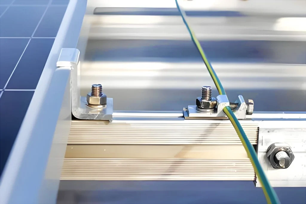
Güneş Panelleri Nasıl Topraklanır??
Genel olarak, Güneş panelleri üzerindeki topraklama delikleri panel dizileri arasında bağlantı kurmak için kullanılır. İpin her iki ucundaki paneller metal çerçeveye bağlanır, öncelikle sarı-yeşil güneş enerjili toprak kabloları kullanılıyor.
Panel çerçevelerini topraklamak için, tipik olarak φ10 veya φ12 bakır bağlı çelik çubuklar kullanılır, gömülü 1.5 metre yeraltı.
Güneş panellerinin topraklama direnci 4Ω'u geçmemelidir. Topraklama direnci gereksinimi karşılanmıyorsa, genellikle direnç azaltıcı maddeler eklenir, veya topraklama çubukları toprak direncinin düşük olduğu alanlara gömülür.
Hakkında daha fazla bilgi edinin Güneş Topraklama Kablosu
Güneş Panellerinin Çerçeveleri Neden Bağlanmalı ve Topraklanmalıdır??
Bazı insanlar hem güneş panellerinin hem de onları destekleyen yapıların metal olduğundan dolayı buna inanıyorlar., desteklerin tek başına topraklanması yeterlidir.
Gerçekte, Çoğu güneş paneli alüminyum çerçevesi ve galvanizli veya alüminyum alaşımlı destek kaplanmıştır, topraklama gereksinimlerini karşılamayan. bunlara ek olarak, Güneş panelleri zamanla eskiyebilir, potansiyel olarak aşırı kaçak akımlara veya düşük toprak izolasyon direncine yol açabilir. Güneş paneli çerçeveleri topraklanmamışsa, bir süre kullandıktan sonra, bu invertör arızalarına neden olabilir, PV sisteminin düzgün elektrik üretmesini önlemek.
Güneş paneli çerçevelerini metal desteklere bağlarken, topraklama empedansını azaltmak için metal yüzeylerden oksit tabakasının çıkarılması gerekir, topraklama gereksinimlerini karşıladığından emin olmak.
Fotovoltaik Sistemlerde Topraklama Çubuğu Hangi Malzeme Kullanılmalıdır??
Galvanizli çelik daha ucuzdur, ama birçok kaynaklı bağlantısı var, daha düşük inşaat verimliliğine ve daha yüksek inşaat maliyetlerine neden olur. Saf bakır mükemmel iletkenliğe sahiptir ancak pahalıdır. Bakır bağlı çelik, Yine de, sadece maliyetler 9.4% Galvanizli çelikten daha fazlası ve çok daha uzun bir servis ömrü sunar. Öyleyse, Bakır bağlı çelik elektrik topraklama çubukları genellikle güneş enerjisi sistemlerinde birincil topraklama malzemesi olarak seçilir..
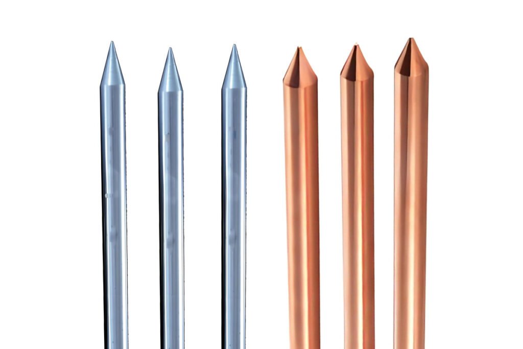
Toprak Çubuklarının Hangi Özellikleri Yaygın Olarak Kullanılır??
Bakır bağlı çelik
Fotovoltaik güç sistemlerinde, bakır bağlı çelik topraklama malzemelerinin yatay topraklama gövdesinde genellikle Φ10-Φ12 bakır bağlı yuvarlak çelik kullanılır, tipik olarak bir üretim uzunluğuna sahip 100 makara başına metre. Topraklama elektrotları Φ14 veya Φ17,2 bakır bağlı çelik çubuklar kullanır.
Bağlantı yöntemi: Termit kaynağı (harici güce veya asetilene gerek yok), Bağlantı malzemeleri için saf bakır kullanılması, kaynak noktalarında korozyon önleyici önlemlere gerek yoktur.
Galvanizli Çelik
Geleneksel topraklama ızgaralarında, Sıcak daldırma galvanizli çelikten imal edilen yatay topraklama gövdeleri genel olarak 50X5 veya 60X6 galvanizli yassı çelik özelliklerinde tasarlanmaktadır., üretim uzunluğuna sahip 6 parça başına metre. Dikey topraklama elektrotları 50X5 sıcak daldırma galvanizli köşebent çelik veya Φ50 galvanizli çelik borular kullanır, topraklama elektrodu uzunluğuna sahip 2.5 parça başına metre.
Bağlantı yöntemi: Elektrikli kaynak, korozyon önleyici işlem gerektiren kaynak noktaları ile, iki kat pas önleyici boya ve bir kat asfalt boyası gibi.
Çıplak Bakır
Saf bakır topraklama malzemeleri için, yatay topraklama gövdesi genellikle 25 kullanır×4, 40×4, 50×5, veya 60×6 mm bakır şeritler, veya S70/S95/S120/S150/S185/S240 mm çıplak bakır teller. Dikey topraklama gövdesi tipik olarak 16 adet kullanır.×2500 mm veya 20×2500 mm bakır çubuklar, veya 50×3000 mm veya 55×2500 mm saf bakır elektrolitik iyon topraklama elektrotları.
Bağlantı yöntemi: Termit kaynağı, ateş çamuru eritme kaynağı, veya sıcakta eriyen kaynak.
Hakkında daha fazla bilgi edinin PV Sistemi için Topraklama Çubuğu
Fotovoltaik Sistemlerde Topraklama Çubukları Nasıl Takılmalıdır??
İnşaat sırasında, topraklama çubuğunun takılması çok esnektir ve sahadaki özel koşullara uyarlanabilir. Çeşitli yöntemler kullanılabilir, elektrikli topraklama çubuklarının ağır çekiçler veya elektrikli çekiçlerle doğrudan toprağa çakılması gibi. Çubuğun çakılamadığı karmaşık toprak koşullarında, topraklama çubuğunu takmadan önce ilk önce bir delik açılabilir.
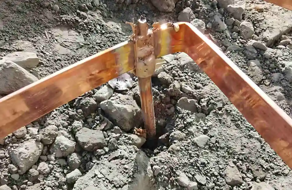
Üniform toprak koşullarında, Tek bir çubuğun montajı ve çakılması için ağır bir çekiç kullanılıyorsa, bir matkap ucu takılması tavsiye edilir (darbeye dayanıklı cıvata) Çubuk derine sürüldüğünde bakır tabakanın zarar görmesini önlemek için çubuğun sivri ucunda. Daha derin topraklama için, İstenilen uzunluğa ulaşmak için konektörler kullanılarak birden fazla çubuk bağlanabilir, iyi elektrik bağlantısının sağlanması.
Derin delmenin zor veya imkansız olduğu durumlarda, kayalara nüfuz etmek için sondaj aletleri kullanılabilir. Sondajdan sonra, Toprak çubuklarını takmanın iki yöntemi vardır:
- Konektörleri kullanarak çubukları istenen uzunluğa bağlayın. İstenilen derinliğe kadar delindikten sonra, deliği direnç azaltıcı bir maddeyle doldurun ve delik dolana kadar su ekleyin.
- Konektörleri kullanarak çubukları istenen uzunluğa bağlayın. İstenilen derinliğe kadar deldikten sonra, Direnç azaltıcı maddeyi suyla karıştırın ve çubuğu tamamen saracak şekilde deliğe dökün.
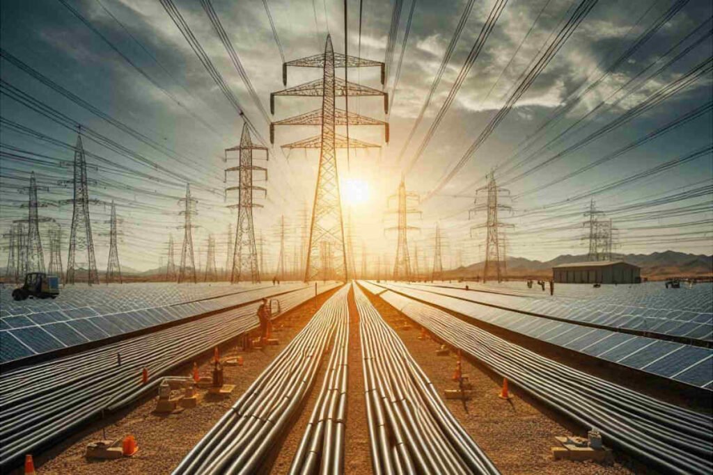
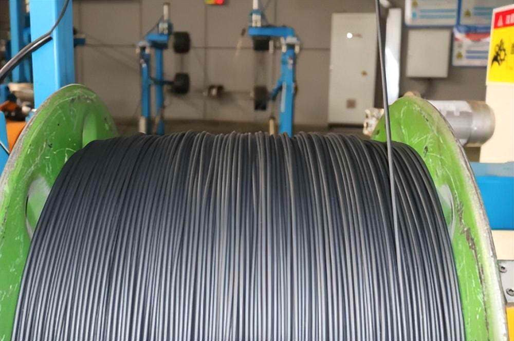
Havai Kablolar, PV Projelerinde Kontrol Kabloları ve Haberleşme Kabloları
Güneş Enerjisi Sistemlerinde Hangi Havai Kablo Kullanılmalı?
Şebekeye bağlı fotovoltaik enerji üretim sistemlerinde, Üretilen DC gücü, invertör tarafından AC gücüne dönüştürüldükten ve AC şebekesine entegre edildikten sonra, Güç iletimi genellikle havai hatlar üzerinden gerçekleştirilir. Tipik olarak, fotovoltaik enerji üretim sistemlerinin şebekeye bağlanma süreci aşağıdaki senaryolarda gerçekleşebilir::
Doğrudan Bağlantı
Küçük dağıtılmış fotovoltaik enerji üretim sistemleri için, konut çatı fotovoltaikleri gibi, DC gücü, invertör aracılığıyla doğrudan AC gücüne dönüştürülebilir ve daha sonra dağıtım hatları aracılığıyla alçak gerilim şebekesine bağlanabilir. Bu durumda, yeraltı alçak gerilim kabloları ve ABC kabloları gibi havai yalıtımlı kablolar kullanılabilir.
Kutu Transformatörleri veya Trafo Merkezi Entegrasyonu ile Bağlantı
Orta veya ticari ölçekli fotovoltaik enerji santralleri kutu tipi trafo merkezlerini kullanabilir (kutusu transformatörler) üretilen DC gücünü invertör aracılığıyla şebeke entegrasyonuna uygun AC gücüne dönüştürmek için, ve ardından baş üstü şebekenin voltaj seviyesine uyacak şekilde kutu transformatörü aracılığıyla voltajı artırın, Havai hatlara bağlanmadan önce.
Büyük ölçekli yere monteli fotovoltaik enerji santralleri, verimli iletim için genellikle voltajı daha yüksek bir seviyeye yükseltmek üzere bir transformatöre ihtiyaç duyar. Bu durumda, güç doğrudan bir trafo merkezine bağlı, daha sonra bunu yüksek voltajlı veya ultra yüksek voltajlı havai şebekelere dağıtır.
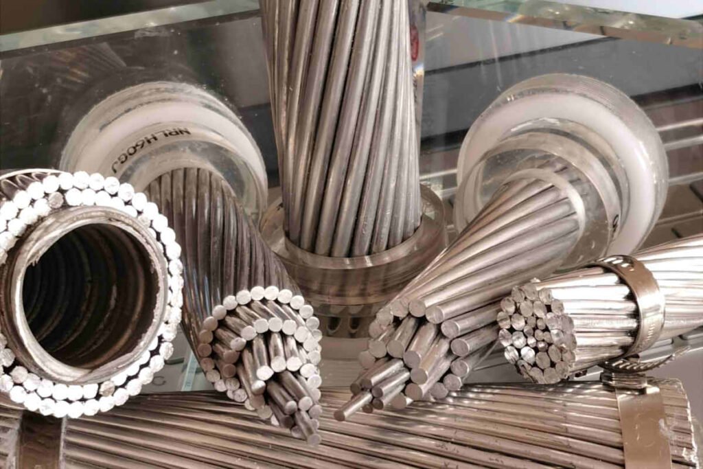
Bu iki senaryoda, santralden şebeke bağlantı noktasına olan mesafe nispeten kısaysa ve yük büyük değilse, AAC kablosu ekonomik bir seçim olabilir. Orta mesafeler için veya daha iyi fiziksel performansın gerekli olduğu yerler için, AAAC kablosu daha iyi bir seçenek olabilir. Uzun mesafeli iletim için veya özel kablo gücü gereksinimlerinin gerekli olduğu yerler için, özellikle havai hatların karmaşık arazilerden geçmesi veya aşırı hava koşullarına dayanması gerektiğinde, ACSR iletkeni en uygun seçim olacaktır.
Hakkında daha fazla bilgi edinin Güneş Sistemi için Havai Kablo
İletişim kabloları, güneş enerjisi üretim sistemi sayımının doğruluğunu etkiler mi?
Güneş enerjisi üretim sisteminde, İletişim kablolarının birincil rolü, kontrol sinyallerini iletmek ve verileri izlemektir, güç çıkışı gibi, sistem durumu, Arıza Alarmları, ve diğer bilgiler. Bu kablolar, elektrik enerjisinin iletimine doğrudan katılmaz. Öyleyse, İletişim kablolarının kendileri, bir güneş enerjisi üretim sistemindeki sayımın doğruluğunu doğrudan etkilemez.
Fakat, İletişim kabloları arızalar yaşarsa (sinyal zayıflaması gibi, parazit yapmak, veya bağlantılardan kesme), İzleme sisteminin verileri doğru bir şekilde alamamasına veya iletememesine yol açabilir, böylece sistem izlemenin hassasiyetini ve zamanlılığını etkiler. Örneğin, Veri iletim gecikmeleri veya hataları, bakım personelinin güç üretim sisteminin gerçek operasyonel durumunu derhal anlamasını veya yanlış veri kaydına yol açmasını engelleyebilir., böylece güç üretiminin istatistiklerini ve analizini etkilemek.
Öyleyse, İletişim kabloları gerçek elektrik enerjisi üretimini etkilemezken, Sistemin etkili yönetimi ve bakımı için çok önemlidir.. Bu dolaylı olarak, güneş enerjisi üretim sisteminin genel performans değerlendirmesi ve verimlilik optimizasyonu ile ilgilidir.. Güneş enerjisi üretim sisteminin güvenilir izlenmesini ve verimli çalışmasını sağlamak için iletişim kablolarının kalitesinin ve uygun şekilde bakımının sağlanması şarttır..
Hakkında daha fazla bilgi edinin PV Sistemi için İletişim ve Kontrol Kablosu
Güneş Enerjisi Projelerinde Kablo Yönlendirmesine İlişkin Yasal ve Düzenleyici Gereksinimler
Mevzuata Uygunluğu Anlamak
Bir güneş enerjisi projesini planlarken ve yürütürken, güvenliği sağlamak için çeşitli yasal ve düzenleyici gerekliliklere uymak önemlidir, yeterlik, ve yerel mevzuata uyum, ulusal, ve uluslararası standartlar. Düzenleyici kurumlar ve politikalar, güneş enerjisi sistemlerinin kurulumunu ve işletilmesini düzenler, kabloların yönlendirilmesi ve seçimi dahil. Bu gereksinimleri anlamak, güneş enerjisi projenizin başarılı bir şekilde tamamlanması için çok önemlidir..
Temel Düzenleyici Kurumlar ve Standartlar
Ulusal Elektrik Kodu (NEC)
Amerika Birleşik Devletleri'nde, Ulusal Elektrik Yasası (NEC) elektrik kablolarının ve ekipmanlarının güvenli kurulumuna yönelik standardı belirler. Madde 690 NEC'in özellikle güneş fotovoltaik konusunu ele alması (PV) sistemler, kablolama yöntemleri gibi hususları kapsayan, topraklama, ve aşırı akım koruması. NEC kurallarına uymak, kablo yönlendirmenizin güvenlik ve performans standartlarını karşılamasını sağlar.
Uluslararası Elektroteknik Komisyonu (IEC)
Uluslararası Elektroteknik Komisyonu (IEC) tüm elektrik için uluslararası standartlar geliştirir, elektronik, ve ilgili teknolojiler. IEC 62548:2016 Güneş PV dizilerinin tasarımı ve kurulumu için yönergeler sağlar, kablo yönetimi ve yönlendirme dahil. Uluslararası projeler için genellikle IEC standartlarına uygunluk gereklidir.
Yerel Bina Kodları
Yerel inşaat kuralları, güneş enerjisi kurulumları için ek gereklilikler getirebilir, kablo yönlendirme dahil. Bu kodlar bölgeye göre önemli ölçüde değişiklik gösterebilir, bu nedenle yerel yetkililere danışmak ve ilgili tüm düzenlemelere uygunluğu sağlamak çok önemlidir..
Kablo Yönlendirme için En İyi Uygulamalar
Uygun Etiketleme ve Dokümantasyon
Tüm kabloların uygun şekilde etiketlendiğinden ve kapsamlı belgelerin muhafaza edildiğinden emin olun. Bu, kablo yönlendirme şemalarını içerir, Kullanılan kabloların özellikleri, muayene ve onayların kayıtları ve kayıtları. Doğru dokümantasyon mevzuata uygunluğu kolaylaştırır ve gelecekteki bakımı kolaylaştırır.
Boru ve Tepsilerin Kullanımı
Yönlendirme için kanallar ve kablo tepsileri kullanmak kabloları fiziksel hasarlardan koruyabilir, elektrik arızası riskini azaltmak, ve kurulumun genel güvenliğini artırın. Boruların ve tepsilerin ilgili standartları karşıladığından ve düzgün şekilde takıldığından emin olun.
Topraklama ve Bağlama
Güneş enerjisi sistemlerinin güvenliği ve performansı için uygun topraklama ve bağlama kritik öneme sahiptir. Topraklama yöntemlerinin NEC ile uyumlu olduğundan emin olun, IEC, ve yerel standartlar. Buna uygun topraklama iletkenlerinin kullanılması da dahildir, konnektörler, ve çubuklar, ve tüm metalik bileşenlerin yeterince bağlanmasının sağlanması.
Düzenli Denetimler ve Bakım
Kablo yönlendirmesinin düzenleyici gerekliliklerle uyumlu kalmasını ve güvenli ve verimli bir şekilde çalışmaya devam etmesini sağlamak için düzenli denetimler ve bakım önemlidir.. Sorunları belirlemek ve çözmek için periyodik denetimler planlayın, fiziksel hasar gibi, giymek, veya korozyon.
Kablo Satın Alma Konusunda Temel Tavsiyeler
Sistem Gereksinimlerinizi Anlayın
Kablo satın almadan önce, Güneş sisteminizin gereksinimlerini net bir şekilde anlamak hayati önem taşıyor. Sistemin boyutunu göz önünde bulundurun, kullanılan bileşen türleri, ve çevresel koşullar. Seçtiğiniz kabloların beklenen elektrik yükünü kaldırabileceğinden ve kurulum yerinizin özel koşullarına uygun olduğundan emin olun..
Kalite ve Sertifikasyona Önem Verin
Her zaman TÜV gibi saygın standartlar tarafından sertifikalandırılmış yüksek kaliteli kabloları tercih edin, UL, veya IEC. Sertifikalı kablolar dayanıklılık açısından test edilmiştir, emniyet, ve performans, endüstri standartlarını karşıladıklarından emin olmak. Sertifikalı kabloların kullanılması güç kaybı gibi olası sorunların önlenmesine yardımcı olur, aşırı ısınma, veya yangın tehlikeleri.
Doğru Kablo Tiplerini Seçin
Güneş enerjisi uygulamaları için özel olarak tasarlanmış kabloları seçin. DC uygulamaları için, H1Z2Z2-K ve PV1-F gibi PV kabloları, UV radyasyonuna karşı dirençleri nedeniyle idealdir, sıcaklık değişimleri, ve mekanik stres. AC uygulamaları için, uygun alçak ve orta gerilim kabloları kullandığınızdan emin olun.
Çevresel Faktörleri Göz önünde bulundurun
Kurulum sahasındaki çevre koşullarını dikkate alın. Sert hava koşullarına maruz kalan kablolar, UV radyasyonu, veya aşırı sıcaklıklar bu koşullara dayanıklılıkları için seçilmelidir. Uygun izolasyon ve koruyucu önlemler kabloların ömrünü uzatacak ve sistem verimliliğini koruyacaktır.
Doğru Kurulum ve Bakımı Sağlayın
Doğru kurulum, doğru kabloları seçmek kadar önemlidir. Kablo yönlendirme için en iyi uygulamaları takip edin, topraklama, ve fiziksel hasarı ve elektrik arızalarını önlemek için koruma. Güneş enerjisi sisteminizin sürekli güvenliğini ve performansını sağlamak için düzenli bakım ve denetimler şarttır..
Mevzuata Uyum Planı
Yerelin farkında olun, ulusal, ve güneş enerjisi projeniz için geçerli olan uluslararası düzenlemeler. Yasal sorunlardan kaçınmak ve sisteminizin güvenliğini ve güvenilirliğini sağlamak için kablo seçiminizin ve kurulumunuzun bu standartlara uygun olduğundan emin olun..
Son Düşünceler
Güneş enerjisi projeniz için doğru kabloları seçmek için zaman ve kaynak yatırımı uzun vadede karşılığını verir. Kaliteli kablolar verimli güç iletimi sağlar, bakım maliyetlerini azaltmak, ve sisteminizin genel güvenliğini ve güvenilirliğini artırın. Bu kılavuzda özetlenen yönergeleri ve en iyi uygulamaları izleyerek, Güneş enerjisi kurulumunuzun başarısına katkıda bulunacak bilinçli kararlar verebilirsiniz.
Hatırlamak, İyi tasarlanmış bir güneş enerjisi sistemi sadece paneller ve invertörlerden ibaret değildir; bu bileşenleri bağlayan kablolar da aynı derecede önemlidir. Kaliteye öncelik verdiğinizden emin olun, uyumluluk, ve güneş enerjisi sisteminizin tüm potansiyelinden yararlanmak için doğru kurulum.